


6
901915
VENTED NATURAL GAS LOGS
TESTING BURNER FOR
LEAKS
1. Generously apply soapy solution to all
connections.
WARNING: Never check for
gas leaks with open flame.
2. Light the burner with the shutoff valve
no more than half open and holding a
match slightly in front of the pan (see
Lighting Instructions, page 7).
3. Inspect all connections for bubbles, raw
gas odor, or flame from any area other
than the burner (leaks). If leaks are de-
tected, shut off the gas valve immedi-
ately. Tighten, or reassemble the loose
connection(s) using pipe joint com-
pound until burner system is leak free.
4. When the burner is tested and leak free,
observe the individual tongues of flame
on the burner.
Note:
The burner design
includes more ports on the outside of the
bar. Make sure that all ports are clear
and producing flame evenly across the
burner. If any ports appear blocked, clear
them by removing the burner manifold
and reaming the ports with a modified
paper clip or other suitable tool.
5. When finished testing, turn the gas
shutoff valve OFF to extinguish all
flames.
ADDING PAN MATERIAL
1. Open the bags of ash bed material (ver-
miculite) and spread it evenly across the
burner pan to the top. You may over-
flow the front and sides of the pan to
cover the entire pan and connecting
hardware. If using optional GA9050 or
GA9150 valve, do not cover valve with
pan material.
2. Open the glowing embers and evenly
cover the ash bed material (vermicu-
lite) in the burner pan.
INSTALLATION
Continued
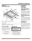
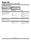
Figure 5 - Checking Gas Joints
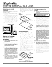
HEARTH KIT ASSEMBLY
AND INSTALLATION
Kit Assembly
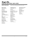
1. Unscrew burner inlet fitting from
burner manifold.
2. Place burner manifold in pan with
threaded opening facing open knock-
out plug (see Figure 6). Make sure the
burner ports face downward.
3. Using thread sealant (resistant to the ac-
tion of propane/LP gas) on larger end
of fitting, screw the burner inlet fitting
through hole and into burner manifold.
Tighten using a wrench. If using pro-
pane/LP gas, follow instructions in-
cluded in optional GA9050 valve kit
or GA9150 valve kit for installation and
operation.
4. Using thread sealant on the male
threads, install the burner connection
fittings into the 1/8" NPT holes on each
side of the burner manifold.
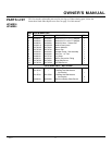
Test Pressures Equal To or Less Than
1/2 PSIG (3.5 kPa)
1. Close equipment shutoff valve (see Fig-
ure 5).
2. Pressurize supply piping system by either
using compressed air or opening main gas
valve located on or near gas meter.
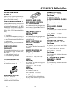
3. Check all joints from gas meter to equip-
ment shutoff valve (see Figure 5). Apply
mixture of liquid soap and water to gas
joints. Bubbles forming show a leak.
4. Correct all leaks at once.
Gas Meter
Equipment Shutoff
Valve
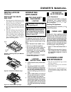
Installation and Gas Connection
1. Place the burner pan assembly in the cen-
ter of the fireplace floor. Make sure the
inlet end of the pan faces the gas supply.
2. Thread the gas supply fitting to the
fireplace gas supply pipe. Use thread
sealant.
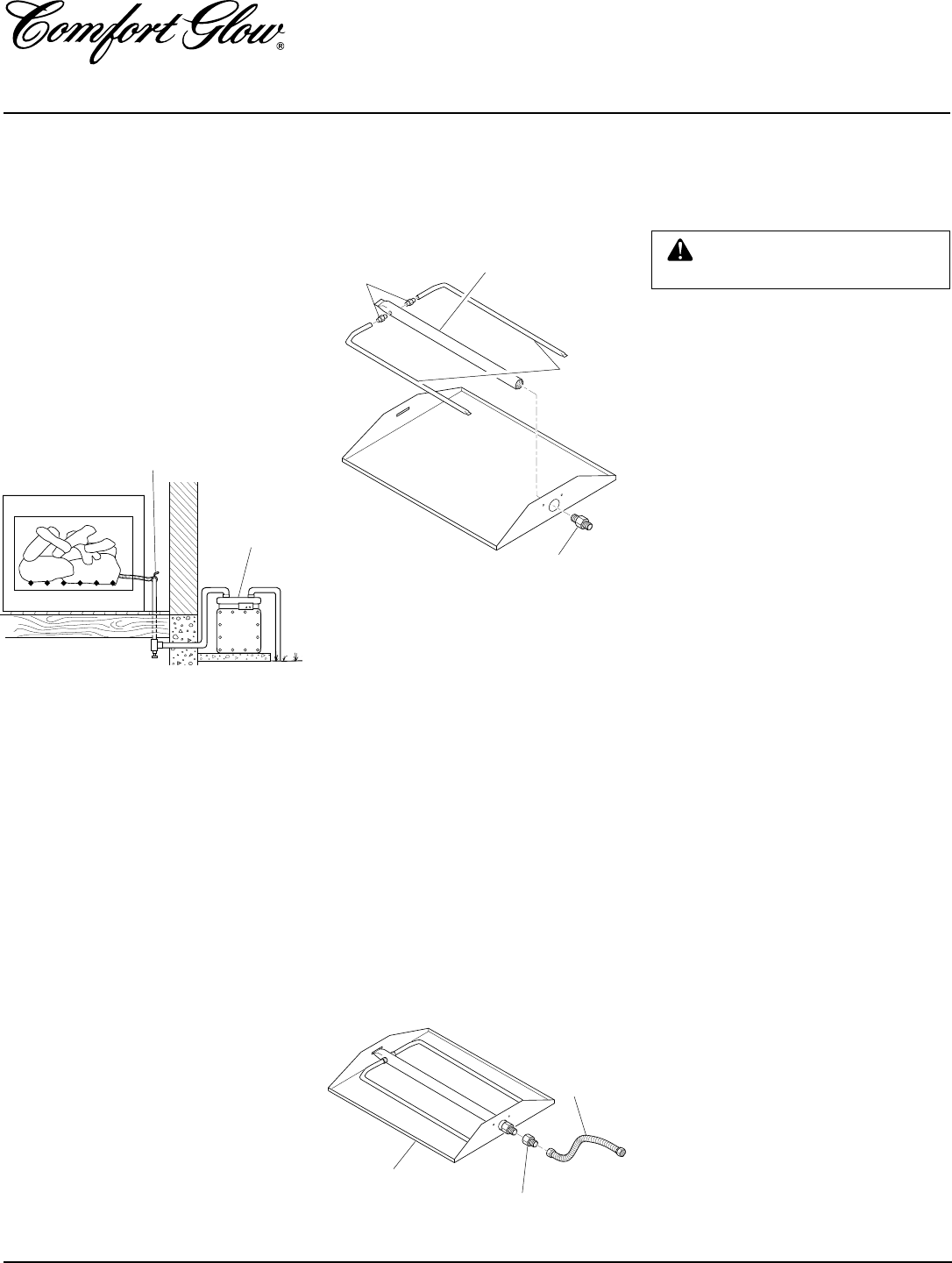
3. Install adapter fitting onto the burner
inlet fitting using thread sealant on
male threads of burner inlet fitting
(see Figure 7). Adjust to most conve-
nient position.
4. Install the gas connector tube to the gas
supply fitting. Carefully shape tube to
attach to adapter fitting. Be careful not
to cause kinks in tube.
5. Using the 1/4" x #8 provided, install
the cover over the inlet fitting.
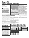
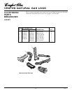
Adapter Fitting
Gas
Connector
Tube
Burner Pan
Assembly
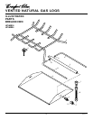
Figure 6 - Installing Burner
Burner Inlet
Fitting
Burner Manifold
Burner
Connection
Fittings
Side
Burners
Figure 7 - Connecting Gas to Appliance
5. Press the right and left side burners onto
the burner connection fittings. The
burner porting should face downward
(see Figure 6).