


112157-01A
15
15
For more information, visit www.desatech.com
For more information, visit www.desatech.com
OPERATING HEATER
Continued
TO TURN OFF GAS
TO APPLIANCE
1. Remove front panel [for 6,000 (1.8 kW) and 10,000 (2.9 kW)
Btu/Hr heater see Figure 11, page 9, for 20,000 Btu/Hr (5.9
kW) heater, see Figure 14 page 10].
2. Follow steps 1 through 5 under Lighting Instructions,
page 14.
3. With control knob pressed in, strike match. Hold match to
pilot until pilot lights.
4. Keep control knob pressed in for 30 seconds after pilot is
lit. After 30 seconds, release control knob. Follow step 8
under Lighting Instructions, page 14.
5. Replace front panel.
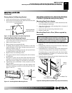
Shutting Off Heater
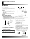
1. Press in and turn control knob clockwise
Clockwise
to the OFF
position.
2. Turn off all electric power to the appliance if service is to
be performed.
Shutting Off Burner Only (pilot stays lit)
Turn control knob clockwise
Clockwise
to the PILOT position.
MANUAL LIGHTING
PROCEDURE
OPERATING HEATER
To Turn Off Gas To Appliance
Thermostat Control Operation (Thermostat Models Only)
Manual Lighting Procedure
INSPECTING BURNER
Pilot Flame Pattern
Burner Flame Pattern
The thermostatic control used on these models differs from
standard thermostats. Standard thermostats simply turn on and
off the burner. The thermostat used on this heater senses the
room temperature. The thermostat adjusts the amount of gas
flow to the burner. This increases or decreases the burner flame
height. At times the room may exceed the set temperature. If so,
the burner will shut off. The burner will cycle back on when room
temperature drops below the set temperature. The control knob
can be set to any heat level between 1 and 5.
Note:
The thermostat sensing bulb measures the temperature of
air near the heater cabinet. This may not always agree with room
temperature (depending on housing construction, installation
location, room size, open air temperatures, etc.). Frequent use of
your heater will let you determine your own comfort levels.
THERMOSTAT CONTROL
OPERATION (THERMOSTAT
MODELS ONLY)
INSPECTING BURNER
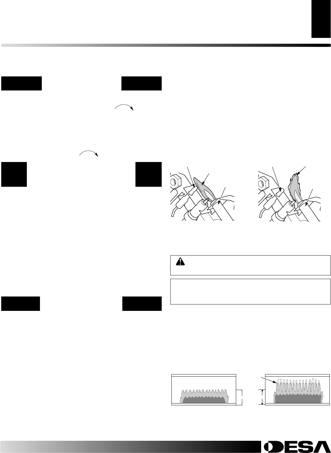
Check pilot flame pattern and burner flame pattern often.
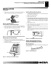
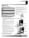
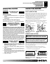
PILOT FLAME PATTERN
Figure 29 shows a correct pilot flame pattern. Figure 30 shows an
incorrect pilot flame pattern. The incorrect pilot flame is not
touching the thermocouple. This will cause the thermocouple to
cool. When the thermocouple cools, the heater will shut down.
If pilot flame pattern is incorrect, as shown in Figure 30
• turn heater off (see To Turn Off Gas to Appliance, column 1)
• see Troubleshooting, pages 18 through 20
Note:
The pilot flame on natural gas units will have a slight curve,
but flame should be blue and have no yellow or orange color.
Figure 30 - Incorrect Pilot Flame
Pattern
Figure 29 - Correct Pilot
Flame Pattern
Thermocouple
Pilot Burner
Pilot
Burner
Thermocouple
Blue Flame
Yellow Flame
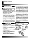
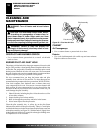
BURNER FLAME PATTERN
WARNING: If yellow tipping occurs, your heater
could produce increased levels of carbon monoxide.
NOTICE: Do not mistake orange flames with yellow
tipping. Dust or other fine particles enter the heater
and burn causing brief patches of orange flame.
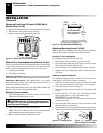
Figure 31 shows a correct burner flame pattern. Figure 32 shows an
incorrect burner flame pattern. The incorrect burner flame pattern
shows yellow tipping of the flame. It also shows the flame higher
than 1/2 the glass panel height.
If burner flame pattern is incorrect, as shown in Figure 32
• turn heater off (see To Turn Off Gas to Appliance, column 1)
• see Troubleshooting, pages 18 through 20
Figure 31 - Correct Burner
Flame Pattern
Figure 32 - Incorrect Burner
Flame Pattern
(Models GCN6 and GCP6 will be
lower due to lower input rating)
1/2 GLASS HEIGHT
Yellow
Tipping