


111162-01A
32
For more information, visit www.desatech.com
For more information, visit www.desatech.com
TECHNICAL SERVICE
You may have further questions about installation, operation, or
troubleshooting. If so, contact DESA Heating Products’ Technical
Service Department at 1-866-672-6040. When calling, please have
your model and serial numbers of your heater ready.
You can also visit DESA Heating Products’ technical services web
site at www.desatech.com.
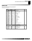
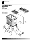
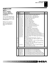
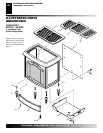
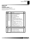
REPLACEMENT PARTS
Note:
Use only original replacement parts. This will protect your
warranty coverage for parts replaced under warranty.
PARTS UNDER WARRANTY
Contact authorized dealers of this product. If they can’t supply
original replacement part(s), call DESA Heating Products’ Techni-
cal Service Department at 1-866-672-6040. When calling DESA
Heating Products, have ready
• your name and address
• model and serial numbers of your heater
• how heater was malfunctioning
• type of gas used (propane/LP or natural gas)
• purchase date
Usually, we will ask you to return the part to the factory.
PARTS NOT UNDER WARRANTY
Contact authorized dealers of this product. If they can’t supply original
replacement part(s), call DESA Heating Products at 1-866-672-6040 for
referral information. When calling DESA Heating Products, have ready
• model number of your heater
• the replacement part number
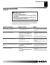
SERVICE HINTS
When Gas Pressure Is Too Low
• pilot will not stay lit
• burners will have delayed ignition
• heater will not produce specified heat
• propane/LP gas supply may be low (propane/LP only)
You may feel your gas pressure is too low. If so, contact your local
propane/LP or natural gas supplier.
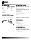
SPECIFICATIONS
WIRING DIAGRAM
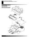
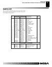
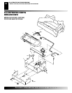
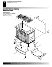
REPLACEMENT PARTS
SERVICE HINTS
TECHNICAL SERVICE
SPECIFICATIONS
(F)SVYD18P(R) (F)SVYD18N(R)
Btu (Variable) 16,000/30,000 16,000/30,000
Type Gas Propane/LP Only Natural Only
Ignition Piezo Piezo
Pressure Manifold 8" W.C. 3.5" W.C.
Inlet Gas Pressure (in. of water)
Maximum 14" 10.5"
Minimum* 11" 5"
Shipping Weight 28 lbs. 28 lbs.
* For input adjustment
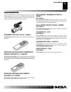
WIRING DIAGRAM
(SVYD18PR and FSVYD18PR Series Remote-
Ready Models Only)
Note
: For proper operation of optional accessories, the wires from
the switch to the control must be connected exactly as shown.
A
UTO
O
F
F
O
N
Thermopile