107172-01J
20
For more information, visit www.desatech.com
For more information, visit www.desatech.com
A
U
T
O
O
F
F
ON
Thermopile
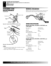
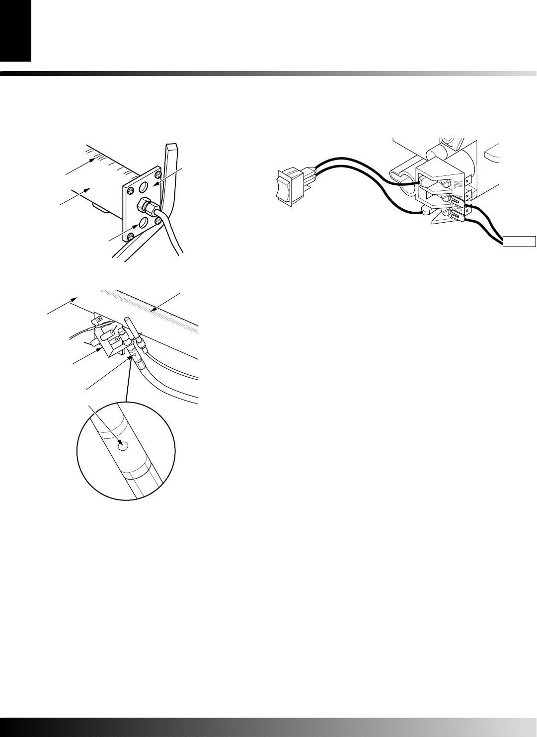
WIRING DIAGRAM
Note
: For proper operation of optional accessories, the wires from
the switch to the control must be connected exactly as shown.
SPECIFICATIONS
MODELS EFS33NR, EFS33NRA, VSGF33NR, and
VSGF33NRA
Btu (Variable) 20,000/33,000
Type Gas Natural Gas Only
Ignition Piezo
Pressure Manifold 3.5" W.C.
Inlet Gas Pressure (in. of water)
Maximum 10.5"
Minimum* 5"
Shipping Weight 122 lbs.
* For input adjustment
MODELS EFS33PR, EFS33PRA, VSGF33PR, and
VSGF33PRA
Btu (Variable) 20,000/33,000
Type Gas Propane/LP Only
Ignition Piezo
Pressure Manifold 7.9" W.C.
Inlet Gas Pressure (in. of water)
Maximum 13"
Minimum* 11"
Shipping Weight 122 lbs.
* For input adjustment
CLEANING AND MAINTENANCE
Cleaning Burner Injector Holder and Pilot Air Inlet Hole (Cont.)
Logs
WIRING DIAGRAM
SPECIFICATIONS
LOGS
• If you remove logs for cleaning, refer to Installing Logs, pages
14 and 15, to properly replace logs.
• Replace log(s) if broken or chipped (dime-sized or larger).
Figure 42 - Injector Holder On Outlet Burner Tube
Burner
Tube
Injector Holder
Primary Air
Inlet Holes
Ports/Slots
Figure 43 - Pilot Inlet Air Hole
Burner
Tube
Pilot
Assembly
Pilot Air
Inlet Hole
Ports/Slots
CLEANING AND
MAINTENANCE
Continued


