


www.desatech.com
111076-01F 5
INSTALLATION
Continued
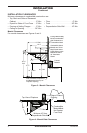
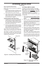
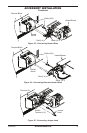
BUILT-IN INSTALLATION
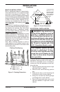
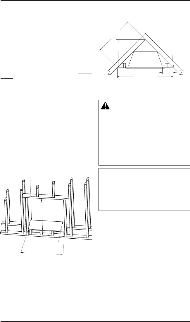
Built-in installations require a framed enclo-
sure constructed of 2" x 4" or heavier lumber
and sized in accordance with Figure 5. This
allows unit to slide into opening and be nailed
to stud at sides and top nailing anges. These
anges accept 5/8" drywall or plywood board
to nish unit ush to face. Optional trim ac-
cessories are available that will extend 1/2"
over rough edge of wall opening (see Acces-
sories, page 25).
IMPORTANT: If installing a perimeter trim kit,
you must install shoulder screws before insert-
ing replace into opening. See instructions
included with trim kit. If installing a mantel,
you must follow clearance instructions (see
Installation Clearances, page 4).
A hearth extension is suggested for a more
pleasing appearance. The replace may be
raised on a wood or non-combustible platform
supporting its entire width and depth and
extending in front of the replace as long as
louvers are not obstructed.
Note: When installing replace in cold cli-
mates against a non-insulated exterior wall,
wall must be fully insulated in accordance with
local building code.
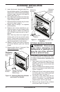
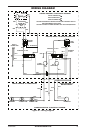
VE32 = 34
5
/
8
"
VE36 = 41
1
/
4
"
VE32 = 15
7
/
8
"
VE36 = 17
1
/
4
"
VE32 = 32
5
/
8
"
VE36 = 36
1
/
4
"
Platform/Subflooring
Figure 5 - Framing Dimensions
VE32 = 37
5
/
8
"
VE36 = 42
3
/
8
"
VE32 = 26
5
/
8
"
VE36 = 29
3
/
8
"
VE32 = 52
3
/
4
"
VE36 = 58
1
/
4
"
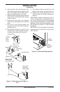
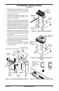
11
5
/
8
"
These Dimensions
Allow for 11
5
/
8
" of
Clearance to Side
Wall of Fireplace
and 10' Clearance
to Perpendicular
Side Walls
Figure 6 - Corner Dimensions
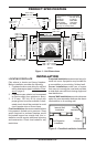
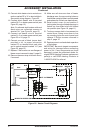
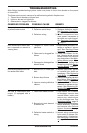
ELECTRICAL INSTALLATION
WARNING: Any electrical re-
wiring of this appliance must be
done by a qualied electrician.
This wiring must be done in ac-
cordance with local codes and/or
in the U.S.A. with the current, Na-
tional Electrical Code ANSI/NFPA
No 70 and in Canada with CSA
C22.1 Canadian Electric code.
This replace should be con-
nected to a dedicated 15 Amp,
circuit as other appliances may
cause the circuit breaker to trip
or fuse to blow when replace
is in operation.
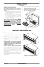
A junction box with universal strain adaptor is
provided to hard wire unit to a 15 amp, 120
Volt 60 Hz grounded circuit. If necessary,
junction box may be relocated to route sup-
ply to left side.
1. Remove 2 screws and outer cover on right
side (see Figure 7, page 6).
2. Remove inner screw securing junction
box.
3. Slide junction box up until mounting tab
is lined up to notch in outer cabinet.
4. Swing box out and slip retaining ange
out through slot in outer cabinet.
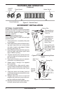
5. Remove 2 screws and outer cover on left
side and reattach on right side of outer
cabinet.