


22
106394
DIRECT-VENT FIREPLACE (NATURAL/PROPANE/LP)
DVFH34, DVFH34P
REMOVING/REPLACING
GLASS DOOR
CAUTION: Do not operate this
fireplace with a broken glass door
panel or without the glass door
panel securely in place. For re-
placement part information see
Replacement Parts
, page 33.
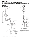
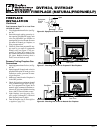
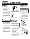
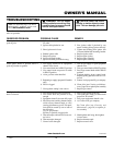
Figure 48 - Removing/Replacing Glass Door
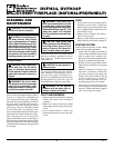
Figure 47 - Removing Top Louver Panel
You must remove glass door to install op-
tional brick liners, logs, lava rock, and em-
ber material.
Glass
Door
Assembly
Screw
Lower Bracket for
Glass Door Assembly
1. Remove the upper louver panel by lift-
ing upward and out (see Figure 47).
2. Remove the screws from the three tabs
at the top of the glass door while hold-
ing door securely keeping it from fall-
ing forward.
3. Grasp door by both sides and ease it
upward off of the lower bracket (see
Figure 48).
4. To replace glass door, follow the above
instructions in reverse.
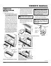
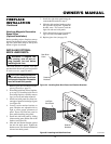
W
R
Feed wires through
rectangular slots
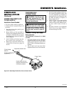
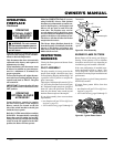
Figure 45 - Back View of Thermostat Base
Terminal “W”
Terminal “R”
Figure 46 - Thermostat Base Terminals
“W” and “R”
4. Route the wire through openings pro-
vided on the sides of the fireplace to a
convenient location to mount your ther-
mostat (no outside wall).
IMPORTANT:
The wire may be short-
ened but must not be lengthened.
The thermostat should be mounted 54"
above the floor in a location where there
is good air circulation. Avoid heat
sources such as lamps, direct sunlight,
fireplace, or heat and air conditioning
ducts.
5. Gently remove the cover of the ther-
mostat from the base. Grasp the sides
of the cover firmly and pull to separate
from the base.
6. Feed the electrical wires through the
rectangular slots (from the back) on
each side of the base (see Figure 45).
WARNING: Do not connect
this thermostat to a power source.
Electrical shock and/or fire haz-
ard will occur.
7. Connect one bare wire end to each ter-
minal (“W” and “R”) of the thermostat
base (see Figure 46).
8. Install the base to the wall with screws
provided with thermostat.
9. Move the temperature adjustment back
and forth to insure the bimetal is free
from restrictions.
10. Replace the cover onto the base. (Upon
installation, the thermostat must be al-
lowed to stabilize at room temperature
for a minimum of 30 minutes for proper
operation.)
11. Set the temperature adjustment to the
desired setting.
This thermostat has been electronically
calibrated at the factory. No adjustment
or leveling is necessary.
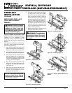
FIREPLACE
INSTALLATION
Continued
Top Louver
Panel
INSTALLING OPTIONAL
WALL MOUNT SWITCH
GWMS2
NOTICE: The GWMS2 includes
25' of wire for installation. Your
fireplace includes 15' of wire for
accessory installation. Choose the
length that best fits your needs
when installing this accessory.
1. Connect one terminal of the provided
wire for the wall switch to the TPTH
terminal on the valve. Connect remain-
ing wire terminal to the TH terminal
on the valve. Make sure that the wire
terminals are in the positions on the unit
as pictured in Figure 41, page 21. If
wires are not connected as shown the
switch will not work.
2. Route the wire through openings pro-
vided on the sides of the fireplace to a
convenient location to mount your switch.
3. Connect one bare wire end to each of the
terminals of the GWMS2 wall switch.
4. Install the wall switch and cover in the
wall.