


13
105843
OWNER’S MANUAL
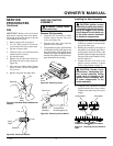
FAN
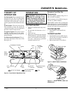
IMPORTANT:
Remove fan from motor
shaft before removing motor from heater.
The weight of the motor resting on the fan
could damage the fan pitch.
1. Remove upper shell (see page 8).
2. Use 1/8" allen wrench to loosen set-
screw which holds fan to motor shaft.
3. Slip fan off motor shaft.
4. Clean fan using a soft cloth moistened
with kerosene or solvent.
5. Dry fan thoroughly.
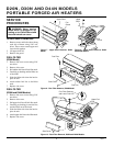
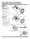
6. Replace fan on motor shaft. Place fan
hub flush with end of motor shaft (see
Figure 28).
7. Place setscrew on flat of shaft. Tighten
setscrew firmly (40-50 inch-pounds/
4.5-5.6 n-m).
8. Replace fan guard and upper shell.
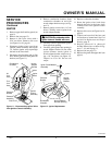
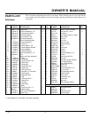
Motor
Shaft
Setscrew
Figure 27 - Fan, Motor Shaft, and Setscrew
Location
Motor
Shaft
Fan
Setscrew
Figure 28 - Fan Cross Section
Fan
Flush
SERVICE
PROCEDURES
Continued
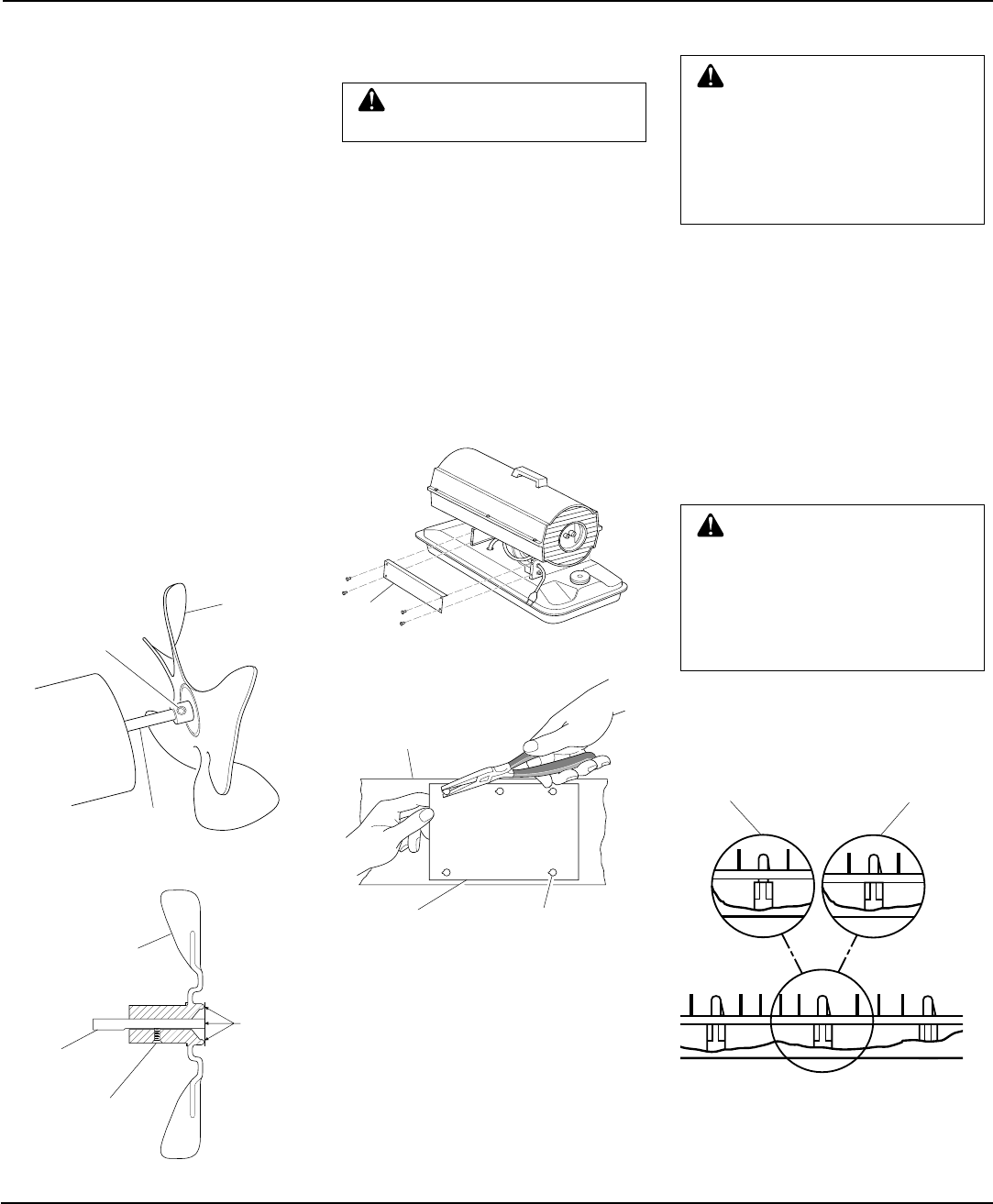
Unacceptable Acceptable
WARNING: Unplug heater
before servicing.
Remove Old Assembly
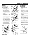
1. Using the 5/16" nut driver or socket
wrench, remove the four side cover
screws (see Figure 29).
2. Disconnect the nine wires from the
ignition control assembly.
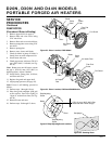
3. Using needle nose pliers, squeeze the tab
on the printed circuit board support and
lift up on the edge of the ignition control
assembly (see Figure 30). Repeat this for
the other four printed circuit board sup-
ports then remove the assembly.
CAUTION: Ignition control
assembly contains electrostatic
components. Handle the assem-
bly by the edges of the printed
circuit board. Do not touch any
of the quick connect terminals
or electronic components.
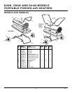
Figure 29 - Removing Cover
Side
Cover
Figure 30 - Removing Circuit Board
Side Cover
Ignition
Control
Assembly
Printed Circuit
Board Supports (5)
Installing the New Assembly
1. Align the five holes in the assembly
with the five printed circuit board sup-
ports in the side cover.
2. Holding the assembly by the edges of
the printed circuit board, apply down-
ward pressure until all five tabs on the
printed circuit board supports springlock
into place. Pull up on assembly to verify
this (see Figure 31).
3. Connect the nine wire leads to the
ignition control assembly as shown
in the wiring diagram on page 21.
Figure 31 - Attaching Circuit Board to
Tabs
CAUTION: Double check
connections. Connecting igni-
tion control assembly wrong
could result in damage to the
ignition control assembly and/
or other components in the
heater assembly.
4. Using the 5/16" nut driver or socket
wrench reinstall side cover to heater.
Tighten screws until snug. Do not over
torque!
Unacceptable Acceptable
IGNITION CONTROL
ASSEMBLY