


901273-01D
8
For more information, visit www.desatech.com
For more information, visit www.desatech.com
INSTALLATION
Hearth Kit Installation (Cont.)
Remote Control Options
Testing Burner for Leaks
Adding Pan Material
INSTALLATION
Continued
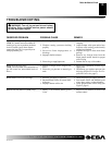
TESTING BURNER FOR LEAKS
1. Generously apply soapy solution to all connections.
WARNING: Never check for gas leaks with
open flame.
2. Light the burner with the shutoff valve no more than half open
and holding a match slightly in front of the pan (see Lighting
Instructions, page 10).
3. Inspect all connections for bubbles, raw gas odor, or flame
from any area other than the burner (leaks). If leaks are de-
tected, shut off the gas valve immediately. Tighten, or reas-
semble the loose connection(s) using pipe joint compound until
burner system is leak free.
4. When the burner is tested and leak free, observe the individual
tongues of flame on the burner.
Note:
The burner design in-
cludes more ports on the outside of the bar. Make sure that all
ports are clear and producing flame evenly across the burner.
If any ports appear blocked, clear them by removing the burner
manifold and reaming the ports with a modified paper clip or
other suitable tool.
5. When finished testing, turn the gas shutoff valve OFF to ex-
tinguish all flames.
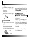
ADDING PAN MATERIAL
1. Open the bag of ash bed material (vermiculite) and spread it evenly
across the burner pan to the top. You may overflow the front and
sides of the pan to cover the entire pan. Do not cover valve.
2. Open the glowing embers and evenly cover the ash bed mate-
rial (vermiculite) in the burner pan.
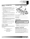
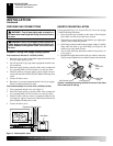
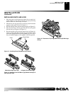
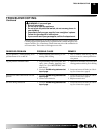
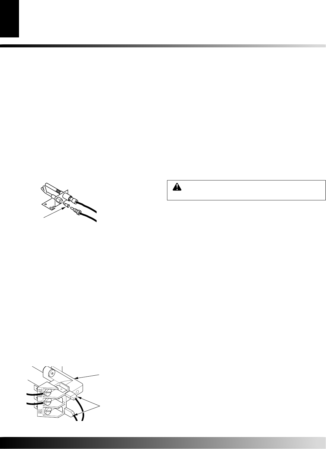
Figure 12 - Installing Propane/LP Pilot Orifice
Pilot
Orifice
Changing Pilot Orifice
The pilot is provided with a natural gas orifice installed. For
propane/LP gas you must remove it and replace it with a propane/LP
orifice. The hardware kit contains an propane/LP orifice with a red
stripe for converting the pilot.
1. Gently loosen and remove the pilot line connection from the
bracket (see Figure 12).
2. Replace the orifice (see Figure 12) with the propane/LP pilot
orifice with the red stripe.
3. Replace and tighten the pilot line to the bracket.
4. Reattach the pilot and piezo ignitor assembly to the valve cover
with the screws previouly removed (see Figure 7, page 7).
Note:
Follow the instructions under the section, Testing Burner
for Leaks.
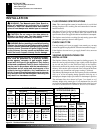
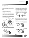
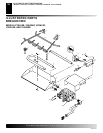
REMOTE CONTROL OPTIONS
GHRC
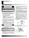
If you are using the GHRC remote control option, you must first
connect the leads of the receiver to the terminal block on the gas
control (see Figure 13).
1. Connect the leads to the male fast-on terminals marked TH
and TPTH.
2. Install a 9V battery (refer to the instructions included with the
GHRC).
3. Install a 9V battery into the hand-held transmitter.
4. Insert the receiver into the simulated log control cover, with
the raised cylinder fitting into the hole in the cover.
5. The cover may be moved aside when operation of the gas con-
trol is necessary.
Figure 13 - Connecting Wire Terminals
Control
Valve
Fast-On
Terminals
GWMS2
When installing the GWMS2 remote wall switch option, follow all
instructions included with the accessory. Connect wires as shown in
Figure 13. You will need to route the wiring away from the gas control
and log set in a way which prevents direct radiant heat on the wires.
No Optional Accessories
If you choose no remote accessories at this time, the provided jumper
wire must be installed to the terminal block on the gas control.
Connect the lead to the fast-on terminals marked TH and TPTH.