


8
104331
BLUE FLAME NATURAL GAS HEATER
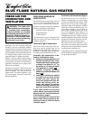
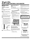
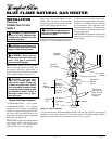
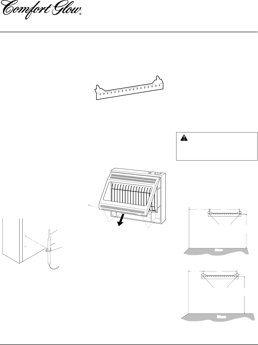
Figure 5 - Attaching Thermostat Sensing
Bulb
Clamp
Thermostat
Sensing
Bulb
THERMOSTAT SENSING
BULB
The thermostat sensing bulb has been
placed inside the heater for protection
during shipping.
Locating Thermostat Sensing
Bulb
1. Remove front panel of heater (see Fig-
ure 7).
2. Locate thermostat sensing bulb just
under burner assembly.
IMPORTANT:
Attach thermostat sensing
bulb to back of heater for proper operation.
Attaching Thermostat Sensing
Bulb
1. Remove thermostat sensing bulb from
holders inside heater. Route through
slot opening in bottom of heater.
2. Place clamp on thermostat sensing bulb
as shown in Figure 5. Clamp is pro-
vided in hardware package.
3. Snap clamp into upper mounting hole
as shown in Figure 5. Mounting hole is
located on lower left edge on back of
heater. Make sure the thermostat sens-
ing bulb is pointing up.
INSTALLATION
Continued
INSTALLING HEATER TO
WALL
Mounting Bracket
Locate mounting bracket in heater carton.
Remove mounting bracket from heater carton.
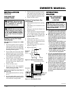
Figure 6 - Bracket Location
Figure 7 - Removing Front Panel Of Heater
Methods For Attaching
Mounting Bracket To Wall
Only use last hole on each end of mounting
bracket to attach bracket to wall. These two
holes are 16 inches apart from their centers.
Attach mounting bracket to wall in one of
two ways.
1. Attaching to wall stud
2. Attaching to wall anchor
Removing Front Panel Of Heater
1. Remove two screws near bottom cor-
ners of front panel.
2. Lift straight up on grill guard until it stops.
Grill guard will slide up about 1/4".
3. Pull bottom of front panel forward, then
downward.
4. Remove cardboard packing from grill
and glass.
Marking Screw Locations
1. Tape mounting bracket to wall where
heater will be located. Make sure
mounting bracket is level.
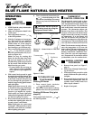
30,000 Btu/Hr Model
20,000 Btu/Hr Models
2. Mark screw locations on wall (see Fig-
ure 8).
Note:
Only mark last hole on each end
of mounting bracket. Insert mounting
screws through these holes only.
3. Remove tape and mounting bracket
from wall.
Figure 8 - Mounting Bracket Clearances
WARNING: Maintain minimum
clearances shown in Figure 8. If
you can, provide greater clear-
ances from floor and joining wall.
Attaching to wall stud: This method pro-
vides the strongest hold. Insert mounting
screws through mounting bracket and into
wall studs.
Attaching to wall anchor: This method
allows you to attach mounting bracket to
hollow walls (wall areas between studs) or
to solid walls (concrete or masonry).
Decide which method better suits your needs.
Either method will provide a secure hold for
the mounting bracket.
18 3/4"
Min.
11"
Min.
16"
Adjoining Wall
Only Insert Mounting
Screws Through Last
Hole On Each End
Floor
16"
18 3/4"
Min.
7 1/4"
Min.
Adjoining Wall
Only Insert Mounting
Screws Through Last
Hole On Each End
Floor