


11
104306
OWNER’S MANUAL
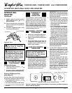
CAUTION: Avoid damage to
regulator. Hold gas regulator with
wrench when connecting it to gas
piping and/or fittings.
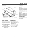
INSTALLATION
Continued
Continued
CONNECTING TO GAS
SUPPLY
NOTICE: A qualified service per-
son must connect heater to gas
supply. Follow all local codes.
Installation Items Needed
Before installing heater, make sure you have
the items listed below.
• piping (check local codes)
• sealant (resistant to propane/LP gas)
• manual shutoff valve *
• test gauge connection *
• sediment trap
• tee joint
• pipe wrench
* An A.G.A. design-certified manual shutoff
valve with 1/8" NPT tap is an acceptable
alternative to test gauge connection. Pur-
chase the optional A.G.A. design-certified
manual shutoff valve from your dealer. See
Accessories, page 21.
CAUTION: Use only new,
black iron or steel pipe. Inter-
nally-tinned copper tubing may
be used in certain areas. Check
your local codes. Use pipe of 1/2"
diameter or greater to allow
proper gas volume to heater. If
pipe is too small, undue loss of
pressure will occur.
Installation must include a manual shutoff
valve, union, and plugged 1/8" NPT tap.
Locate NPT tap within reach for test gauge
hook up. NPT tap must be upstream from
heater (see Figure 12).
Apply pipe joint sealant lightly to male
threads. This will prevent excess sealant
from going into pipe. Excess sealant in pipe
could result in clogged heater valves.
CAUTION: Use pipe joint seal-
ant that is resistant to liquid pe-
troleum (LP) gas.
Install sediment trap in supply line as shown
in Figure 12. Locate sediment trap where it
is within reach for cleaning. Locate sedi-
ment trap where trapped matter is not likely
to freeze. A sediment trap traps moisture
and contaminants. This keeps them from
going into heater controls. If sediment trap
is not installed or is installed wrong, heater
may not run properly.
WARNING: Never connect
heater to private (non-utility) gas
wells. This gas is commonly
known as well-head gas.
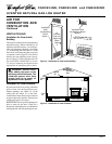
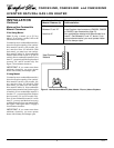
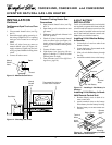
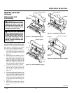
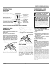
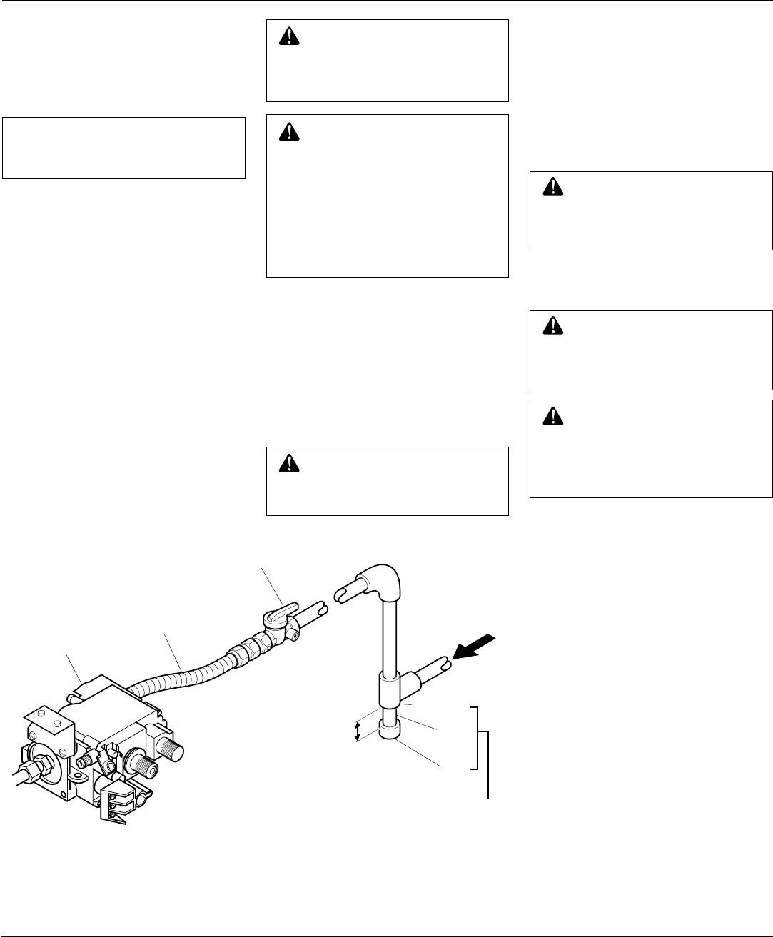
Figure 12 - Gas Connection
* Purchase the optional A.G.A. design-certified manual shutoff valve from your dealer. See
Accessories, page 21.
** Minimum inlet pressure for purpose of input adjustment.
Tee Joint
Pipe
Nipple
Cap
3" Minimum
Sediment
Trap
Gas Control
From Gas Meter
(5" W.C.** to
10.5" W.C.
Pressure)
A.G.A. Design-Certified Manual
Shutoff Valve With 1/8" NPT Tap*
Approved Flexible Gas Hose
(if allowed by local codes)
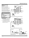
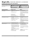
WARNING: Never use an open
flame to check for a leak. Apply a
mixture of liquid soap and water
to all joints. Bubbles forming show
a leak. Correct all leaks at once.
WARNING: Test all gas pip-
ing and connections for leaks
after installing or servicing. Cor-
rect all leaks at once.
CHECKING GAS
CONNECTIONS
Pressure Testing gas Supply
Piping system
Test Pressures In Excess Of 1/2 PSIG
1. Disconnect heater and its individual
manual shutoff valve from gas supply
piping system. Pressures in excess of
1/2 psig will damage heater regulator.
2. Cap off open end of gas pipe where
manual shutoff valve was connected.
3. Pressurize supply piping system by ei-
ther using compressed air or opening
main gas valve located on or near gas
meter.
4. Check all joints of gas supply piping
system. Apply mixture of liquid soap
and water to gas joints. Bubbles form-
ing show a leak.
5. Correct all leaks at once.
6. Re-connect heater and manual shutoff
valve to gas supply. Check re-con-
nected fittings for leaks.