


www.desatech.com
111916-01F
10
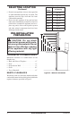
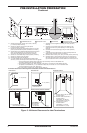
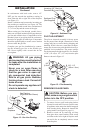
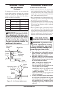
In conformance with local codes, route a 1/2"
NPT gas line towards the appliance coming in
from either the left or right side of the fireplace
(see Figure 13).
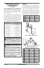
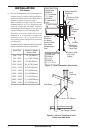
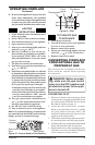
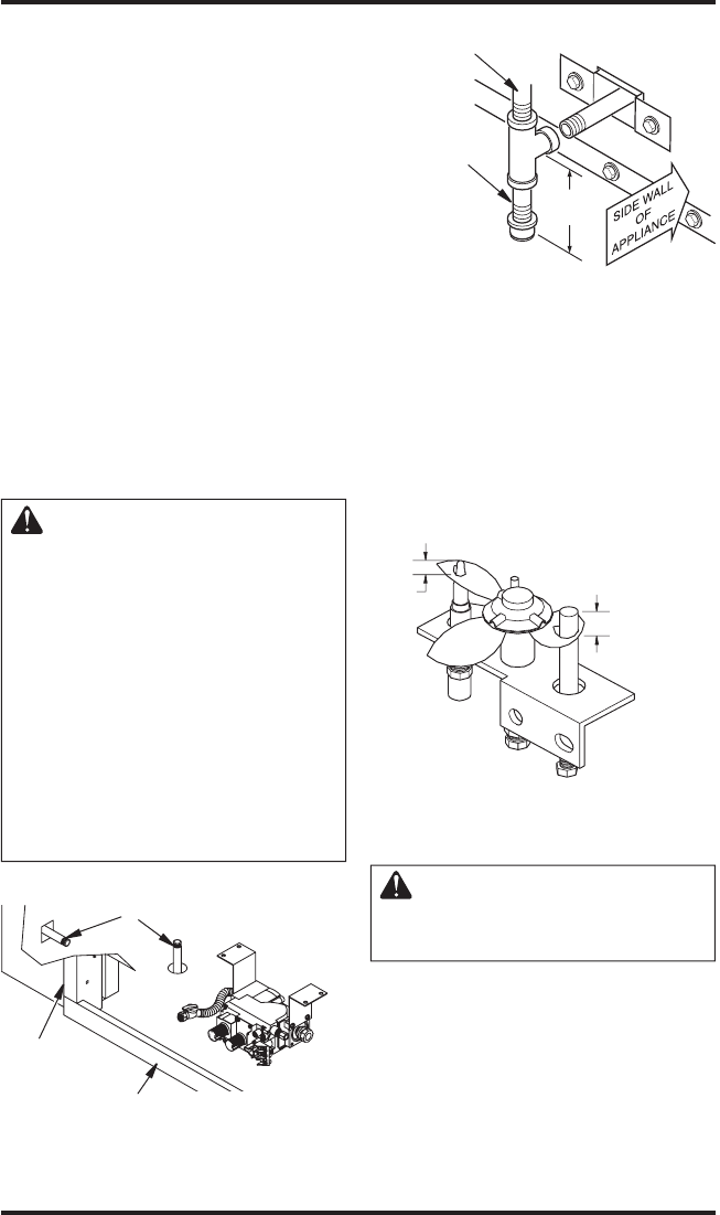
Install a sediment trap between the incoming gas
line and the gas control box (see Figure 14). The
sediment trap should extend down a minimum of
3" (7.62 cm) beyond the center of the pipe.
When routing gas line through conduit sleeve,
make sure to repack insulation to fill gaps between
gas line and conduit sleeve. Compounds used on
threaded joints of gas piping shall be resistant to
the action of propane or natural gas. Compounds
should be applied lightly to ensure excess sealant
does not enter the gas line.
Complete your gas line installation by connect
-
ing the incoming gas line to the flexible gas
line. Secure tightly with a wrench but do not
over-tighten.
WARNING: All gas piping
and connections must be tested
for leaks after the installation is
completed.
Never use an open flame to
check for a leak. After ensuring
that the gas valve is open ap-
ply commercial leak detection
fluid to all gas joints. Bubbles
forming show a leak. Correct all
leaks at once.
Do not operate any appliance if
a leak is detected.
INSTALLATION
Continued
Figure 13 - Gas Line Routing
Gas Routing
(Right Side Not Shown)
Side of
Fireplace
Front Face
Figure 14 - Sediment Trap
Sediment Trap
(Not Supplied)
Incoming 1/2" Gas Line
Permitted By Local Codes
3" Min.
(7.6 cm)
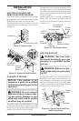
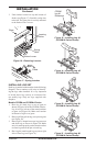
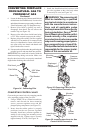
PILOT ADJUSTMENT
The pilot or electrode assembly is factory preset
for the proper flame height. Alterations to these
settings may have occurred during shipping and
handling. If this is the case, some minor readjust-
ments may be necessary and should be done by a
qualified service technician. The proper settings
for the thermopile height should be at a distance
of 3/8" (.95 cm) to 1/2" (1.27 cm) from the pilot
flame as shown in Figure 15.
Figure 15 - Pilot Assembly
1/8"
(0.3cm)
3/8" - 1/2"
(.95cm-1.3cm)
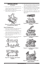
REMOVING GLASS PANEL
CAUTION: Before you pro-
ceed, make sure your gas control
valve is in the OFF position.
1. To remove louvers, pull both spring latches
(located in each end of louver) toward center
of appliance at the same time until disengaged
from locating holes. Repeat for bottom end
spring latches (see Figure 16, page 11).
2. Remove screen rod by removing rod loop
from glass door center bracket. Slide screen
rod either to the left or right of fireplace until
one end is free to completely remove screen
from fireplace.