


-7 - For more information, visit www.desatech.com
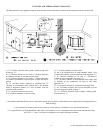
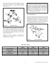
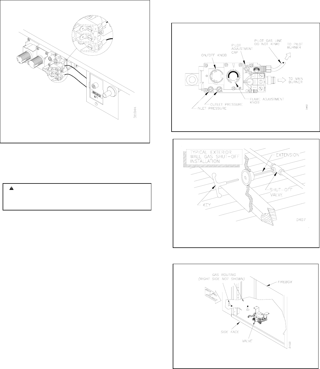
The remote control receiver is factory wired and connected to
the convertible gas valve as shown in figure 11.
GAS SUPPLY TESTING
NOTE: This section is intended as a guide for qualified
technicians installing gas to the appliance.
The appliance and its individual shut-off valve must be
disconnected from the gas supply piping system during any
pressure testing of that system at test pressures in excess of ½
psig (3.5 kPa).
The appliance must be isolated from the gas supply piping
system by closing its individual manual shut-off valve during
any pressure testing of the gas supply piping system at test
pressures equal to or less than ½ psig (3.5 kPa).
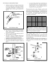
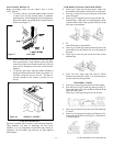
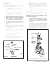
The gas control valve is secured underneath the firebox. Two
1/8 NPT plugged tappings are provided on the gas control
valve for pressure test gauge connections (see figure 12).
GAS LINE HOOK-UP
Gas line hook-up should be done by your gas supplier or
licensed service technician.
NOTE: Before you proceed, make sure your gas supply is off.
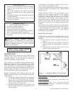
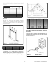
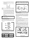
A manual shut-off valve has been included in the fireplace’s
gas supply system. However, consider installing an extra
shut-off valve outside the appliance’s enclosure (check with
local codes), where it can be accessed more conveniently with
a key through a wall as shown in figure 13.
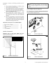
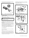
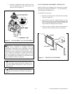
In conformance with local codes, route a ½” NPT gas line
towards the appliance coming in from either the left or right
side of the fireplace (see figure 14).
CAUTION: Do not kink flexible gas line.
WARNING: Do not connect appliance before pressure
testing gas piping. Damage to gas valve may result and a
n
unsafe condition may be created.
Figure 13 GAS LINE HOOK-UP
Figure 14 GAS LINE ROUTING
Figure 11 REMOTE CONTROL RECEIVER
Figure 12 GAS CONTROL VALVE