


-5 - For more information, visit www.desatech.com
VENT INSTALLATION INSTRUCTIONS
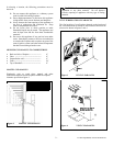
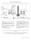
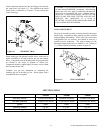
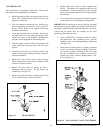
1. Install pipe to fireplace collar adapter located on back
of unit at a 45 deg. Angle. Connect our starting pipe
to a 45 deg. Starting section by sliding it over the
collar adapter on the fireplace. Twist-lock for proper
installation check to insure proper connection (see
figure 5).
2. Once the elbow is properly fastened to the fireplace
adapter, continue to install the remainder of the pipe
for the desired installation.
3. Install every section of the pipe making sure that all
joints are properly twist-locked.
4. After steps 1, 2 and 3 are completed, install the vent
termination. Depending on location of termination,
you may use a vertical or horizontal termination.
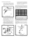
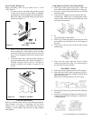
5. Depending on the wall thickness, allow one inch to
protrude from internal wall as shown in figure 6.
6. For vertical venting application, install vertical flue
restrictor into inner collar of fireplace as shown in
figure 5.
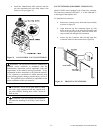
7. An optional siding standoff may be installed between
the vent cap exterior wall. Secure horizontal top to
standoff and then secure the complete assembly to
wall (see figure 6). The vent termination must be
removable for service pipe inspection.
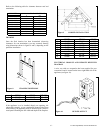
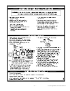
The vent system serves as the “chimney” as well as the
combustion air supply (air intake). The horizontal run must
have a rise of ¼” (6 mm) for every 1 foot (305 mm) of
horizontal run towards the termination. Never allow the vent
to run downward. The maximum horizontal run depends on
the vertical rise from fireplace adapter collar to the vent
termination (see table below).
When installing length of pipe over 3 ft. (914 mm)
horizontally, support the pipe every 3 ft. (914 mm) using
metal straps. Vertical to horizontal pipe must be kept at a one
foot (305 mm) to 4 ft. (1219 mm) ratio with a maximum run
of no more than 20 ft.
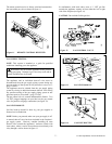
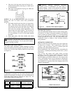
If an offset is necessary in the attic to avoid obstruction, it is
important to support the vent pipe every 3 ft. (914 mm), to
avoid excessive stress on the elbows and possible separation
see figure 7).
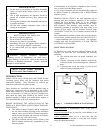
ft mm ft mm
0to1'305
1 305 to 4 1219
2 610 to 8 2438
3 914 to 12 3658
41219to164877
51524to154572
61829to144267
72134to133962
82438to123658
VERTICAL HORIZONTAL
Figure 7 OFFSET ELBOW
WARNING: Vent pipe air space clearances to
combustibles are 1” on all sides except on the horizontal
sections, which require 2” clearances from the top of the
pipe. Where the termination cap penetrates a combustible
wall, 1” air space clearance is required.
Figure 6 VENT TERMINATION
Figure 5 VENT INSTALLATION