


111161-01A
12
For more information, visit www.desatech.com
For more information, visit www.desatech.com
WARNING: Use pipe joint sealant that is resistant
to liquid petroleum (LP) gas.
CAUTION: Avoid damage to regulator. Hold gas
regulator with wrench when connecting it to gas
piping and/or fittings.
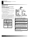
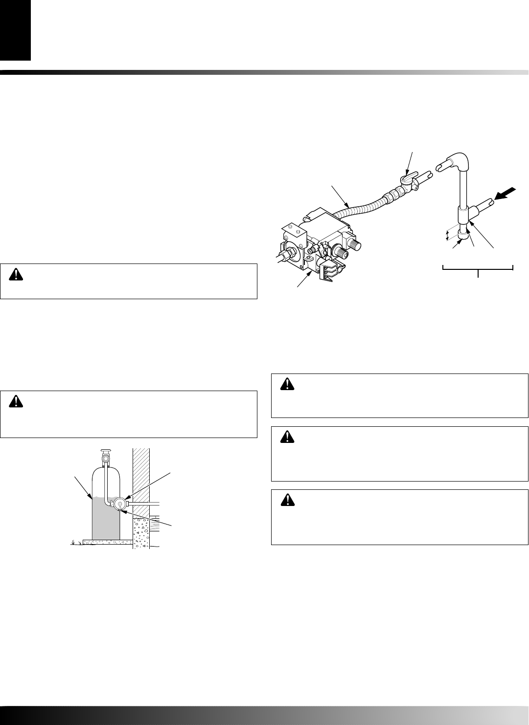
Installation must include an equipment shutoff valve, union, and
plugged 1/8" NPT tap. Locate NPT tap within reach for test gauge
hook up. NPT tap must be upstream from heater (see Figure 14).
IMPORTANT:
Install equipment shutoff valve in an accessible
location. The equipment shutoff valve is for turning on or shutting
off the gas to the appliance.
Check your building codes for any special requierments for locating
equipment shutoff valve to fireplaces.
Apply pipe joint sealant lightly to male NPT threads. This will
prevent excess sealant from going into pipe. Excess sealant in pipe
could result in clogged heater valves.
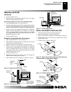
We recommend that you install a sediment trap in supply line as shown
in Figure 14. Locate sediment trap where it is within reach for cleaning.
Install in piping system between fuel supply and heater. Locate
sediment trap where trapped matter is not likely to freeze. A sediment trap
traps moisture and contaminants. This keeps them from going into heater
controls. If sediment trap is not installed or is installed wrong, heater may
not run properly.
INSTALLATION
Continued
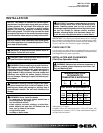
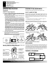
* Purchase the optional CSA design-certified equipment shutoff
valve from your dealer. See Accessories, page 28.
** Minimum inlet pressure for purpose of input adjustment.
Figure 14 - Gas Connection
Cap Pipe Tee
Nipple Joint
3" Minimum
Sediment Trap
Gas
Control
From
External
Regulator
(11" W.C.**
to 14" W.C.
Pressure)
CSA Design-Certified
Equipment Shutoff Valve
With 1/8" NPT Tap*
Approved Flexible Gas Hose
(if allowed by local codes)
Propane/LP
Supply Tank
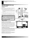
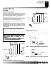
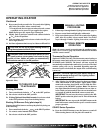
External
Regulator
Vent
Pointing
Down
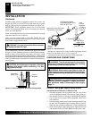
Figure 13 - External Regulator With Vent Pointing Down
WARNING: Never use an open flame to check for
a leak. Apply a noncorrosive leak detection fluid to all
joints. Bubbles forming show a leak. Correct all leaks
at once.
WARNING: Test all gas piping and connections,
internal and external to unit, for leaks after installing
or servicing. Correct all leaks at once.
CHECKING GAS CONNECTIONS
CAUTION: Make sure external regulator has been
installed between propane/LP supply and heater.
See guidelines under
Connecting to Gas Supply
,
page 11.
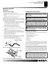
Pressure Testing gas Supply Piping system
Test Pressures In Excess Of 1/2 PSIG (3.5 kPa)
1. Disconnect appliance with its appliance main gas valve (control
valve) and equipment shutoff valve from gas supply piping sys-
tem. Pressures in excess of 1/2 psig will damage heater regulator.
2. Cap off open end of gas pipe where equipment shutoff valve
was connected.
3. Pressurize supply piping system by either opening propane/LP sup-
ply tank valve for propane/LP gas or opening main gas valve lo-
cated on or near gas meter for natural gas, or using compressed air.
4. Check all joints of gas supply piping system. Apply noncorrosive
leak detection fluid to gas joints. Bubbles forming show a leak.
INSTALLATION
Connecting To Gas Supply (Cont.)
Checking Gas Connections