


105522
13
13
SERVICE PROCEDURES
Continued
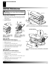
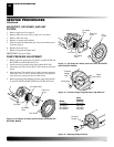
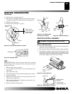
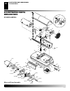
Figure 26 - Sanding Rotor
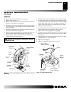
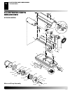
Figure 25 - Gap Adjusting Screw Locations
Gap Adjusting
Screw
Gap Adjusting
Screw
Blade
.076/.101 mm
(.003"/.004") Gap
Measured With
Feeler Gauge
Rotor
Sandpaper
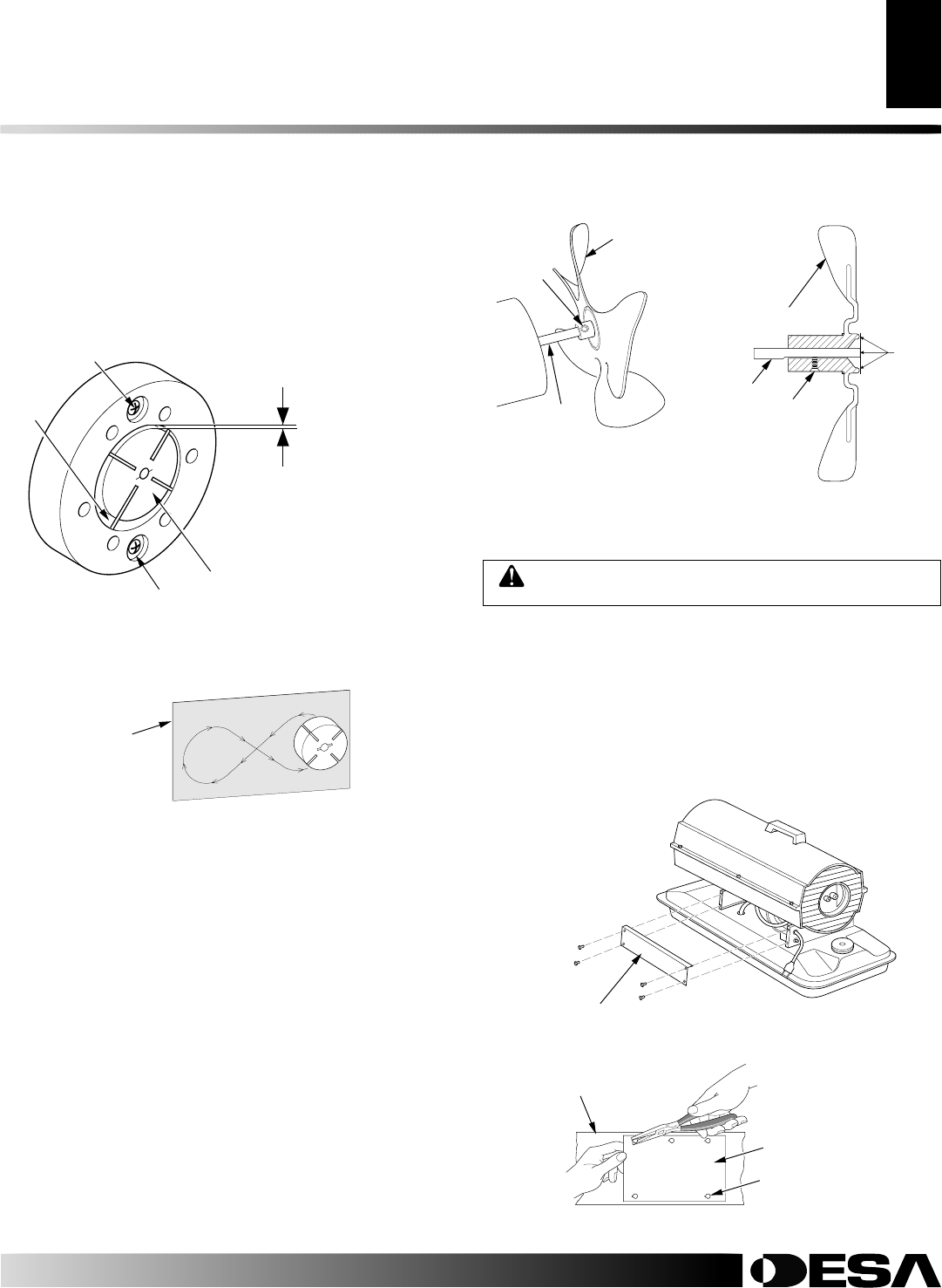
FAN
IMPORTANT:
Remove fan from motor shaft before removing
motor from heater. The weight of the motor resting on the fan could
damage the fan pitch.
1. Remove upper shell (see page 8).
2. Use 1/8" allen wrench to loosen setscrew which holds fan to
motor shaft.
3. Slip fan off motor shaft.
4. Clean fan using a soft cloth moistened with kerosene or solvent.
5. Dry fan thoroughly.
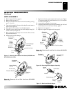
6. Replace fan on motor shaft. Place fan hub flush with end of
motor shaft (see Figure 28).
7. Place setscrew on flat of shaft. Tighten setscrew firmly 4.5 to
5.6 N-m (40 to 50 in-lbs).
8. Replace fan guard and upper shell.
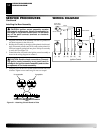
Motor
Shaft
Setscrew
Figure 27 - Fan, Motor Shaft,
and Setscrew Location
Motor
Shaft
Fan
Setscrew
Figure 28 - Fan Cross Section
Fan
Flush
13. Perform steps 1 through 6, page 12.
14. Place fine grade sandpaper (600 grit) on flat surface. Sand ro-
tor lightly in “figure 8” motion four times (see Figure 26).
15. Reinstall insert and rotor.
16. Perform steps 10 through 12, page 12.
IGNITION CONTROL ASSEMBLY
WARNING: Unplug heater before servicing.
Remove Old Assembly
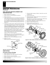
1. Using the 5/16" nut driver or socket wrench, remove the four
side cover screws (see Figure 29).
2. Disconnect the nine wires from the ignition control assembly.
3. Using needle nose pliers, squeeze the tab on the printed circuit
board support and lift up on the edge of the ignition control
assembly (see Figure 30). Repeat this for the other four printed
circuit board supports then remove the assembly.
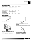
Figure 29 - Removing Cover
Side
Cover
Figure 30 - Removing Circuit Board
Side Cover
Ignition Control
Assembly
Printed Circuit
Board Supports (5)
SERVICE PROCEDURES