


105522
4
VENTILATION
WARNING: Follow the minimum fresh, outside air
ventilation requirements. If proper fresh, outside air
ventilation is not provided, carbon monoxide poison-
ing can occur. Provide proper fresh, outside air ven-
tilation before running heater.
Provide a fresh air opening of at least 2800 square cm (three square
feet) for each 30kw (100,000 Btu/Hr) rating. Provide extra fresh air
if more heaters are being used.
Example:
A 44kw (150,000 Btu/Hr) heater requires one of the
following:
• a two-car garage door [4.9 meter (16 feet) opening] raised 9 cm
(3.5 inches)
• a single-car garage door [2.75 meter (9 feet) opening] raised 15.25
cm (6 inches)
• two, 76 cm (30 inch) windows raised 28 cm (11 inches)
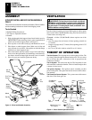
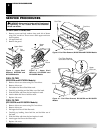
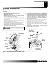
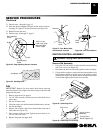
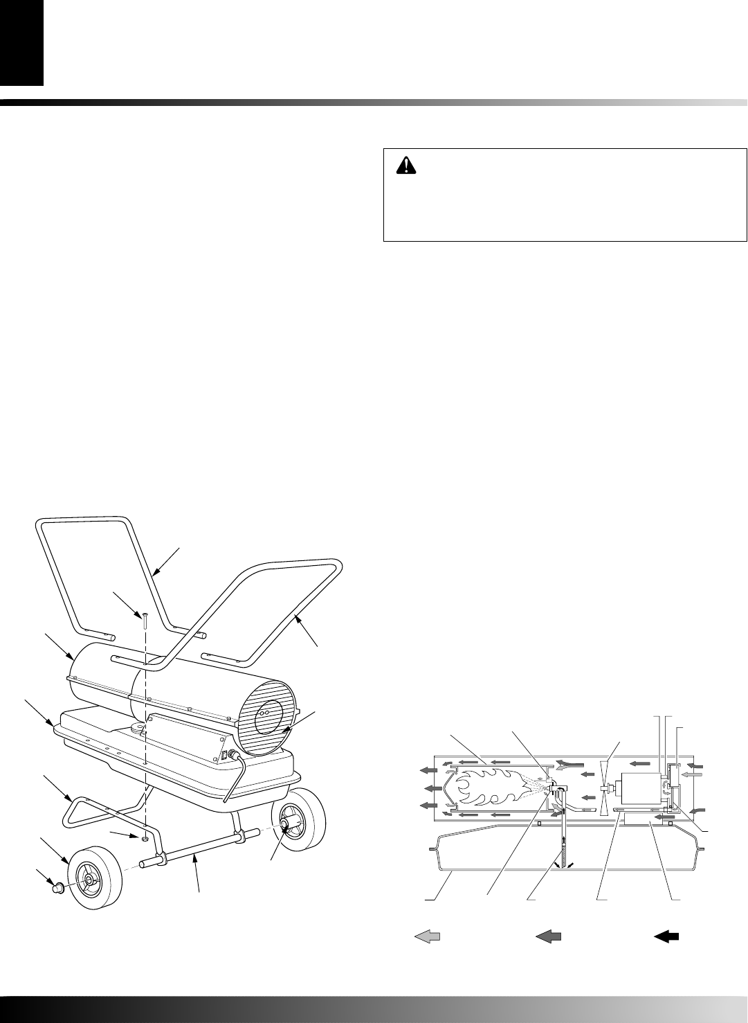
THEORY OF OPERATION
The Fuel System: The air pump forces air through the air line. The
air is then pushed through the burner head nozzle. This air causes
fuel to lift from the tank. A fine mist of fuel is sprayed into the
combustion chamber.
The Air System: The motor turns the fan. The fan pushes air into
and around the combustion chamber. This air is heated and provides
a stream of clean, hot air.
The Ignition System: The ignition control assembly provides
power to the ignitor. This ignites the fuel/air mixture in the combus-
tion chamber.
The Flame-Out Control System: This system causes the heater to
shut down if the flame goes out.
Figure 4 - Cross Section Operational View
Clean
Heated
Air Out
Air
Output
Filter
Air Pump
Cool
Air In
Motor
Screw
Wheel
Support
Frame
Wheel
Cap Nut
Nut
Extended
Hub
Front Handle
Axle
Rear
Handle
Air
Inlet
Fuel Tank
Flange
Hot Air
Outlet
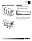
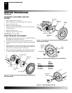
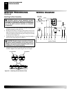
ASSEMBLY
(FOR BY100CEH AND BY150CEH MODELS
ONLY)
These models are furnished with wheels and handles. Wheels, handles,
and the mounting hardware are found in the shipping carton.
Tools Needed
• Medium Phillips Screwdriver
• 3/8" Open or Adjustable Wrench
• Hammer
1. Slide axle through wheel support frame. Install wheels on axle.
IMPORTANT:
When installing wheels, point extended hub of
wheels toward wheel support frame (see Figure 3).
2. Place cap nuts on axle ends. Gently tap with hammer to secure.
3. Place heater on wheel support frame. Make sure air inlet end
(rear) of heater is over wheels. Line up holes on fuel tank flange
with holes on wheel support frame.
4. Place front handle and rear handle on top of fuel tank flange.
Insert screws through handles, fuel tank flange, and wheel sup-
port frame. Attach nut finger tight after each screw is inserted.
5. After all screws are inserted, tighten nuts firmly.
Figure 3 - Wheel and Handle Assembly
Air Intake
Filter
Fan
Combustion
Chamber
Fuel
Filter
Air Line
To Burner
Ignition
Control
Assembly
Air For Fuel
System
Air For
Combustion
And Heating
Fuel
Fuel
Tank
Ignitor
Nozzle
ASSEMBLY
VENTILATION
THEORY OF OPERATION