


www.desatech.com
901746-01E8
INSTALLATION
Continued
CHECKING GAS CONNECTIONS
and connections, internal and
external to unit, for leaks after
-
PRESSURE TESTING GAS SUPPLY
PIPING SYSTEM
1. Disconnect log set and its individual equip-
ment shutoff valve from gas supply piping
system.
2. Cap off open end of gas pipe where equip-
ment shutoff valve was connected.
3. Pressurize supply piping system by either
using compressed air or opening main gas
valve located on or near gas meter.
4. Check all joints of gas supply piping sys-
tem. Apply a noncorrosive leak detection
uid to all joints. Bubbles forming show a
leak.
5. Correct all leaks at once.
6. Reconnect log set and equipment shutoff
valve to gas supply. Check reconnected
ttings for leaks.
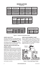
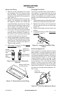
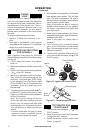
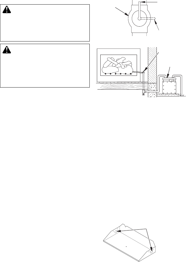
Test Pressures Equal To or Less Than
1. Close equipment shutoff valve (see
Figure 5).
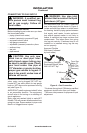
2. Pressurize supply piping system by either
using compressed air or opening main gas
valve located on or near gas meter.
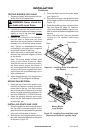
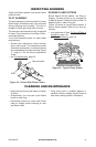
3. Check all joints from gas meter to equip-
ment shutoff valve (see Figure 6). Apply
a noncorrosive leak detection uid to all
joints. Bubbles forming show a leak.
4. Correct all leaks at once.
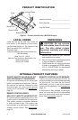
Figure 6 - Checking Gas Joints
Gas Meter
Equipment
Shutoff Valve
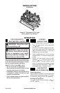
INSTALLATION
Note: The following instructions apply to
both standard single bar burners, as well as
dual ame “U” style burners. Be sure all pipe
threaded connections are tight, and have
thread compound to prevent leaks.
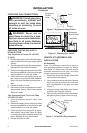
1. Determine which side the gas line will be
coming into the replace.
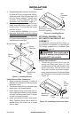
2. Using a hammer and screw driver, remove
knock-out plug from the side of the pan
that corresponds to the gas line (see
Figure 7).
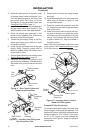
3. Unscrew burner inlet tting from burner
manifold (see Figure 8, page 9).
4. Place burner manifold in pan with thread-
ed opening facing open knock-out plug.
Figure 5 - Equipment Shutoff Valve
Open
Closed
Equipment
Shutoff
Valve
Knock-out
Plugs
Figure 7 - Knock-Out Plug Locations