


www.desatech.com
901746-01E 11
INSTALLATION
Continued
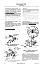
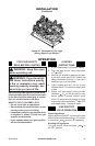
The pilot is provided with a natural gas ori-
ce installed. For propane/LP gas you must
remove it and replace it with an propane/LP
orice. The hardware kit contains an pro-
pane/LP orice with a red stripe for converting
the pilot.
1. Gently loosen and remove the pilot line con-
nection from the bracket (see Figure 16).
2. Replace the injector with the propane/
LP pilot injector with the red stripe (see
Figure 16).
3. Replace and tighten the pilot line to the
bracket.
4. Continue with step 3 under Natural Gas
Installation, page 10.
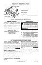
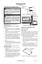
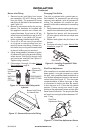
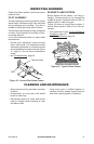
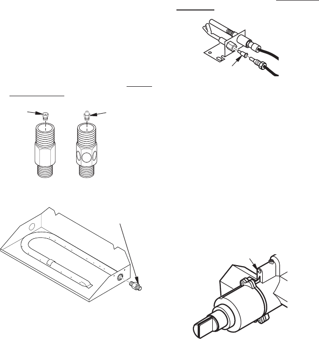
Figure 14 - Burner Inlet Fittings with
Injectors
NATURAL
GAS
FITTING
PROPANE/LP
GAS FITTING
Injector
for Natural
Gas
Injector for
Propane/LP
Gas
1. Remove burner inlet tting from burner
pan assembly. DO NOT remove orice
from this tting. The propane/LP burner
inlet tting is included in the hardware kit
(see Figure 14).
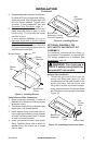
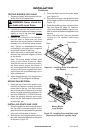
2. Be sure to use correct orice for your ap-
pliance. The hardware kit included with
this appliance contains two orices with
a cone-like shape. If you have an 18" set,
orice for burner inlet tting is red; for a 30"
set, it is black. If you have a 24" log set,
orice is already installed inside tting.
3. For an 18" or 30" set, use a 10 mm socket
or nut driver to remove orice from pro-
pane/LP burner inlet tting. Choose cor-
rect orice for your log set size and install
in place of orice you just removed.
4. Using thread sealant (resistant to action
of propane/LP gas) on larger end of tting,
screw burner inlet tting through hole
and into burner manifold, see Figure 15.
Tighten using a wrench.
5 . Follow steps 1 through 12 under Natural
Gas Installation, page 9.
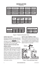
Figure 15 - Remove Burner Inlet FItting
Burner Inlet Fitting
for Natural Gas
Figure 16 - Installing Propane/LP Pilot
Orice
Pilot Orice
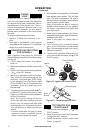
After installation is complete and the unit has
been ignited, it may be necessary to adjust
the pilot. Use a small at-head screwdriver to
turn the ow adjustment screw on the manual
control valve (see Figure 17). Turn the screw
counterclockwise to allow more gas to ow
or clockwise to restrict gas ow. Be careful
to limit the turns to 2
1
/
2
from the fully closed
position. Further turning can result in gas
leaking at the adjustment screw and the pilot
ame size will diminish. The proper pilot ow
will result in a strong blue ame between 1/2"
and 1" long.
Figure 17 - Piliot Flow Adjustment Screw
Pilot Flow
Adjustment Screw