


www.desatech.com
113282-01C 13
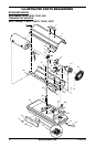
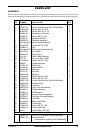
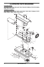
SERVICE PROCEDURES
Continued
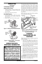
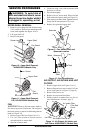
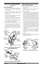
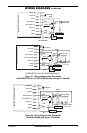
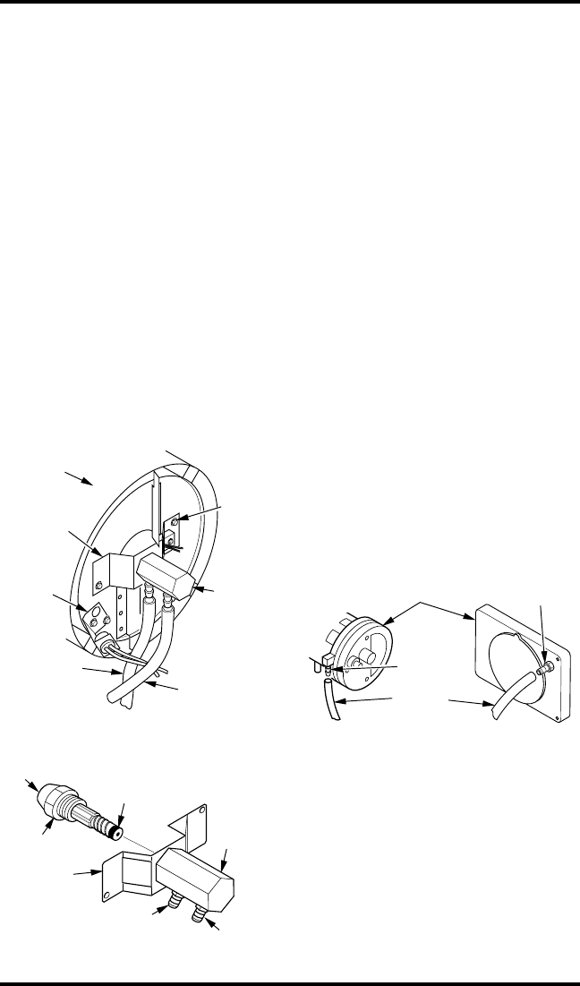
Figure 27 - Removing Air and Fuel Line
Hoses (200 Model Only)
Fuel Line Hose
Nozzle/
Adapter
Assembly
Combustion
Chamber
Nozzle
Adapter
Bracket
Photocell
Bracket
Air Line
Hose
Nozzle
Adapter
Bracket
Screw
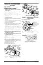
Nozzle Face
Nozzle
Nozzle
Sleeve
Nozzle
Adapter
Bracket
Air Line
Fitting
Fuel Line Fitting
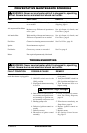
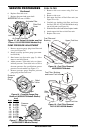
Figure 28 - Nozzle and Nozzle Adapter
Nozzle
Adapter
(For 200 Model Only)
1. Remove combustion chamber and ignitor by
following steps 1 through 7 under Ignitor,
pages 11 and 12.
2. Carefully place the ignitor in a safe location.
3. Remove two nozzle adapter bracket screws
(see Figure 27).
4. Place hex-shaped aluminum nozzle adapter
into vise (do not overtighten).
5. Carefully remove nozzle from nozzle adapter
using 5/8" socket wrench (see Figure 28).
6. Blow compressed air through face of nozzle.
This will remove any debris in nozzle.
7. Inspect nozzle seal for damage.
8. Replace nozzle into nozzle adapter until
nozzle seats. Tighten 80-110 inch-pounds.
9. Attach nozzle adapter bracket to combustion
chamber with two screws removed in step 3.
10. Repeat steps 9 through 16 under Ignitor,
page 11.
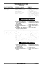
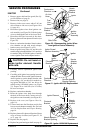
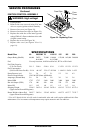
Figure 29 - Air Hose to Barb Fitting
Air Hose
Pump End Cover
Barb
Fitting
110/115/155/165/200
Models
40/50/55/60/70
Models
Barb Fitting
FUEL AND AIR LINE REPLACEMENT
AND PROPER ROUTING
1. Remove upper shell (see Upper Shell Re-
moval, page 9).
2. Remove side cover screws using 5/16" nut
driver (see Figure 18 or 19, page 10).
3. Remove side cover.
4. Inspect fuel and air line hoses for cracks and/
or holes. If fuel line hose is damaged, discon-
nect from nozzle adapter (see Figure 23 or 24,
page 12, or Figure 27) and from fuel filter (see
Fuel Filter, page 10). If air line hose is dam-
aged, disconnect from nozzle adapter (see Fig-
ure 23 or 24, page 12, or Figure 27) and from
barb fitting on pump end cover (see Figure 29).
5. Install new air and/or fuel line. Attach one end
of air line hose to barb fitting on pump end cover
(see Figure 29) and the other end to nozzle
adapter (see Figure 23 or 24, page 12, or Figure
27). Attach one end of fuel line hose to fuel fil-
ter (see Fuel Filter, page 10) and the other end
to nozzle adapter (see Figure 23 or 24, page 12,
or Figure 27).
Note:
Route hoses as shown in see Figure 23
or 24, page 12, or Figure 27, according to
model. Hoses are not to touch photocell
bracket.
6. Replace side cover.
7. Replace upper shell and fan guard (see Upper
Shell Removal, page 9).