


115425-01
6
For more information, visit www.desatech.com
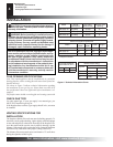
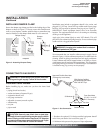
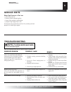
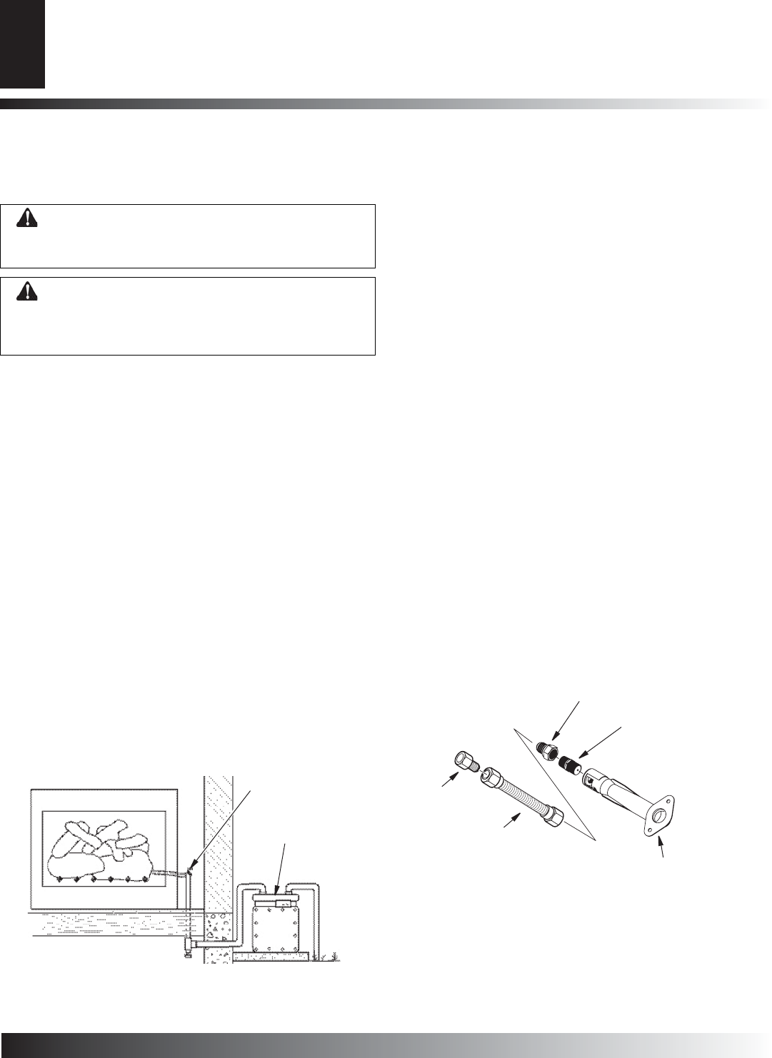
Figure 5 - Checking Gas Joints
HEARTH KIT ASSEMBLY AND INSTALLATION
Kit Assembly - Ramp Pan Burner
1. Determine which side the gas line feeds into the fi replace. This
logset is factory set up for right side (facing) gas feed. If your
gas line is on the right side, go to the Installation and Gas
Connection section below. If your gas line is on the left side
of the fi replace, proceed with steps 2 through 4 below.
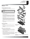
2. Remove the nuts securing the gas inlet venturi to the bottom
of the burner. (see Figure 6).
3. Remove the venturi from the pan taking care not to damage
the gasket between the venturi and the pan.
4. Reverse the direction of the venturi and re-attach to the bottom
of the pan using factory nuts.
Installation and Gas Connection
1. Place the ramp burner assembly in the center of the fi replace
fl oor. Make sure the front of pan faces forward.
2. Thread the gas supply fi tting to the fi replace gas supply pipe.
Use thread sealant.
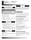
3. Install the gas connector tube to the gas supply fi tting. Carefully
shape tube to attach to adapter fi tting. Be careful not to cause
kinks in tube.
4. Attach opposite end of gas connector tube to the gas inlet fi tting
on the end of the venturi.
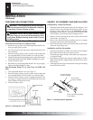
WARNING: Test all gas piping and connections,
internal and external to unit, for leaks after installing
or servicing. Correct all leaks at once.
WARNING: Never use an open fl ame to check
for a leak. Apply a noncorrosive leak detection fl uid
to all joints. Bubbles forming show a leak. Correct
all leaks at once.
CHECKING GAS CONNECTIONS
Pressure Testing Gas Supply Piping System
Test Pressures In Excess Of 1/2 PSIG (3.5 kPa)
1. Disconnect log set and its individual equipment shutoff valve
from gas supply piping system.
2. Cap off open end of gas pipe where equipment shutoff valve
was connected.
3. Pressurize supply piping system by either using compressed
air or opening main gas valve located on or near gas meter.
4. Check all joints of gas supply piping system. Apply noncorrosive
leak detection fl uid to gas joints. Bubbles forming show a leak.
5. Correct all leaks at once.
6. Reconnect log set and equipment shutoff valve to gas supply.
Check reconnected fi ttings for leaks.
Test Pressures Equal To or Less Than 1/2 PSIG (3.5
kPa)
1. Close equipment shutoff valve (see Figure 5).
2. Pressurize supply piping system by either using compressed
air or opening main gas valve located on or near gas meter.
3. Check all joints from gas meter to equipment shutoff valve
(see Figure 5). Apply noncorrosive leak detection fl uid to gas
joints. Bubbles forming show a leak.
4. Correct all leaks at once.
INSTALLATION
Continued
Gas Meter
Equipment Shutoff
Valve
INSTALLATION
Checking Gas Connections
Hearth Kit Assembly and Installation
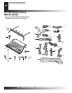
Burner Orifi ce
(Factory Installed)
Burner Inlet Venturi (Attached
to Pan Bottom)
Gas Connector
Tube
Figure 7 - Connecting Gas to Appliance
Adapter
Fitting
Burner Inlet Fitting
(Factory Installed)