


108795-01K
19
19
For more information, visit www.desatech.com
For more information, visit www.desatech.com
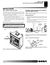
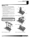
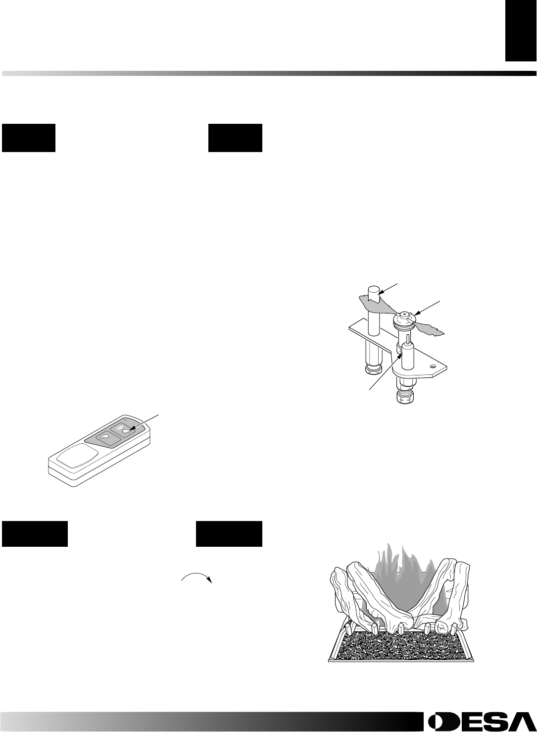
Thermopile
Pilot Burner
Ignitor
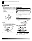
OPTIONAL HAND-HELD
REMOTE OPERATION
Note:
The receiver and hand-held remote control kit must be
purchased separately (see Accessories, page 29). Follow installa-
tion instructions on pages 11 and 12 of this manual.
1. After lighting, let pilot flame burn for about one minute.
Turn control knob to ON position. Slide the selector switch
to the REMOTE position.
Note:
The burner may light if
hand-held remote was on when selector switch was last
turned off. You can now turn the burner on and off with
the hand-held remote control unit.
IMPORTANT:
Do not leave the selector switch in the RE-
MOTE or ON position when the pilot is not lit. This will
drain the battery.
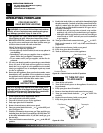
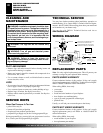
2. Press the control button on the hand-held remote to turn
the burner on. Press the control button again to turn burner
off (see Figure 41).
3. To Lock press both buttons on remote control until light
stops flashing. Remote is now locked. If the fire is on it will
be turned off automatically. In the locked state, the light
will not light up when any button is pressed.
4. To Unlock press both buttons together on remote control
until light stops flashing. The remote is now unlocked.
Shutting Off Heater
Press in and turn control knob clockwise
Clockwise
to the OFF
position.
Shutting Off Burner Only (pilot stays lit)
Turn remote control wall switch to the OFF position.
INSPECTING BURNERS
Check pilot flame pattern and burner flame patterns often.
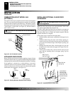
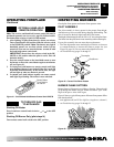
PILOT ASSEMBLY
The pilot assembly is factory preset for the proper flame height.
Alterations may have occurred during shipping and handling. The
pilot is located on the back right hand side of the burner.
The height of the thermopile must be 3/8" to 1/2" above the pilot flame.
The flame from the pilot burner must extend beyond the thermopile.
If your pilot assembly does not meet these requirements:
• Turn the adjustment screw marked pilot clockwise to decrease
or counterclockwise to increase the flame to proper size (see
Figure 39, page 18). Do not remove the adjustment screw.
• see Troubleshooting, pages 21 through 23
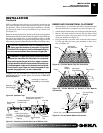
Figure 42 - Correct Pilot Flame Pattern
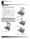
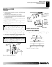
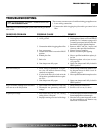
BURNER FLAME PATTERN
Burner flames will be steady; not lifting or floating. Flames should
go up through the middle of logset. Flames should not "spill" to the
edges of the pan or sides of the logset.
Figure 43 shows a typical flame pattern. If burner flame pattern differs
from that described:
• turn appliance off (see To Turn Off Gas to Appliance, column 1)
• see Troubleshooting, pages 21 through 23
Figure 43 - Typical Flame Pattern
OPERATING FIREPLACE
Continued
OPERATING FIREPLACE
Optional Hand-Held Remote Operation
To Turn Off Gas to Appliance
INSPECTING BURNERS
Pilot Assembly
Burner Flame Pattern
TO TURN OFF GAS
TO APPLIANCE
Figure 41 - On/Off Hand-Held Remote Control Unit GHRCB
Control Button
Turns Burners
On and Off