


8
102388
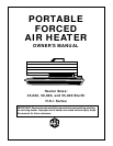
PORTABLE FORCED AIR HEATERS
35,000, 50,000, And 55,000 Btu/Hr H.S.I. Series
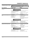
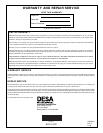
PUMP ROTOR
(Procedure if Rotor is Binding)
1. Remove upper shell (see page 6).
2. Remove filter end cover screws using
5/16" nut-driver.
3. Remove filter end cover and air filters.
4. Remove pump plate screws using 5/16"
nut-driver.
5. Remove pump plate.
6. Remove rotor, insert, and blades.
7. Check for debris in pump. If debris is
found, blow out with compressed air.
8. Install insert and rotor.
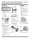
9. Check gap on rotor. Adjust to .003"/.004"
if needed (see Figure 15).
Note:
Rotate rotor one full turn to in-
sure the gap is .003"/.004" at tightest
position. Adjust if needed.
10. Install blades, pump plate, air filters,
and filter end cover.
11. Replace fan guard and upper shell.
12. Adjust pump pressure (see Pump Pres-
sure Adjustment, page 6).
Note:
If rotor is still binding, proceed
as follows.
13. Perform steps 1 through 6 above.
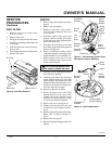
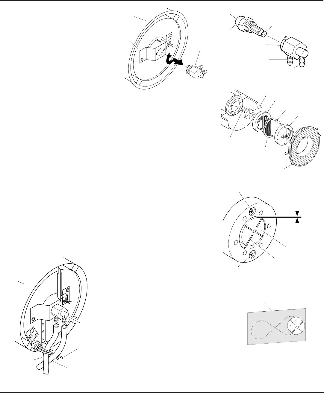
14. Place fine grade sandpaper (600 grit) on
flat surface. Sand rotor lightly in “figure
8” motion four times (see Figure 16).
15. Reinstall insert and rotor.
16. Perform steps 10 through 12 above.
Sandpaper
Figure 16 - Sanding Rotor
Figure 15 - Gap Adjusting Screw Locations
Figure 14 - Rotor Location
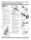
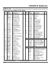
NOZZLE
1. Remove upper shell (see page 6).
2. Remove fan (see page 6).
3. Remove fuel and air line hoses from
nozzle assembly (see Figure 11).
4. Turn nozzle adapter 1/4 turn to left and
pull toward motor to remove (see Fig-
ure 13).
5. Place nozzle adapter into vise and
lightly tighten.
6. Carefully unscrew nozzle from the
nozzle adapter using 5/8" socket
wrench (see Figure 14).
7. Blow compressed air through face of
nozzle. This will free any dirt in
nozzle area.
8. Inspect nozzle seal for damage.
9. Replace nozzle into nozzle adapter un-
til nozzle seats. Tighten 1/3 turn more
using 5/8" socket wrench (40-45 inch-
pounds).
10. Attach nozzle assembly to burner strap.
11. Attach and route fuel and airline hoses
to nozzle assembly as shown (see Fig-
ure 11). Route photocell wires as shown
in Figure 11.
12. Replace fan (see page 6).
13. Replace fan guard and upper shell (see
page 6).
Figure 13 - Nozzle and Nozzle Adapter
Figure 11 - Removing Air and Fuel Line
Hoses
Figure 12 - Removing Nozzle Assembly
SERVICE
PROCEDURES
Continued
Fuel Line
Hose
Nozzle/
Adapter
Assembly
Combustion
Chamber
Air Line Hose
Nozzle
Adaptor
Bracket
Nozzle
Adapter
Combustion
Chamber
Nozzle Face
Nozzle
Nozzle Adapter
Air Line
Fitting
Fuel Line Fitting
Nozzle Seal
.003"/.004"
Gap
Measured
With
Feeler
Gauge
Blade
Rotor
Gap Adjusting
Screw
Gap Adjusting Screw
Insert
Rotor
Air Output
Filter
Blade
Pump Plate
Air Intake Filter
Filter End
Cover
Fan Guard
Photocell
Wires