


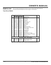

7
901910
OWNER’S MANUAL
For more information, visit www.desatech.com
INSTALLATION
Continued
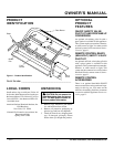
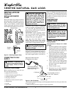
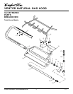
Figure 6 - Kit Assembly
HEARTH KIT ASSEMBLY
AND INSTALLATION
Kit Assembly
Note:
Be sure all pipe threaded connections
are tight, and have thread compound to
prevent leaks.
1. Remove burner inlet fitting from front
burner (installed in burner pan, see Fig-
ure 6).
2. Make sure ports on front burner are fac-
ing the front (open side) of burner pan.
Refit if needed.
3. Using thread sealant (resistant to the
action of propane/LP gas) on larger end
of fitting, screw the burner inlet fitting
through the hole and into the front burner
(see Figure 6). Tighten using a 7/8"
wrench.
4. Apply thread sealant compound to the
3/8" male threads of the burner inlet
fitting. Thread the manifold block (see
Figure 6) onto the burner inlet fitting.
Use the bottom hole of the block.
Test Pressures Equal To or Less Than
1/2 PSIG (3.5 kPa)
1. Close equipment shutoff valve (see Fig-
ure 5).
2. Pressurize supply piping system by either
using compressed air or opening main gas
valve located on or near gas meter.
3. Check all joints from gas meter to equip-
ment shutoff valve (see Figure 5). Apply
mixture of liquid soap and water to gas
joints. Bubbles forming show a leak.
4. Correct all leaks at once.
Gas Meter
Equipment Shutoff Valve
5. Apply thread sealant to the 1/8" brass
pipe nipple and thread it onto the mani-
fold block. Tighten with a 7/16" wrench.
6. Slip the air restrictor over the 1/8" pipe
nipple. Apply thread sealant to the male
threads and install the rear burner
nozzle onto the fitting. Tighten with a
9/16" wrench.
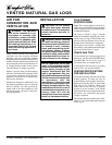
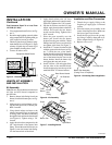
7. Place the grate assembly over the
burner pan. Install the rear burner
bracket onto the grate with the 2 black
Phillips head #10 screws provided. Do
not tighten at this time (see Figure 7).
8. Install the “U” burner from the left side
with the open end in the front (see Fig-
ure 7). Hold the rear of the burner
higher than the bracket. Slide the burner
over the air restrictor fitting. Lower the
rear of the burner into the slots on the
burner bracket. Install the burner clip
and tighten the nuts and screws.
9. Install 3/8 flare x 3/8 male pipe elbow
into the inlet of the manifold block.
Install the pipe plug into the top of the
manifold block. Use thread sealant.
Burner
Inlet
Fitting
Front
Burner
Pipe
Nipple
Air Restrictor
Manifold
Block
Rear Burner Nozzle
Grate
Burner Pan
Burner
Bracket
Burner
Clip
Pipe Elbow
Pipe
Plug
Figure 7 - Installing Burner
Continued
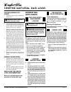
Installation and Gas Connection
1. Thread the gas supply fitting to the
fireplace gas supply pipe. Use thread
sealant.
2. Place the burner pan assembly in the
center of the fireplace floor. Make sure
the front of pan faces forward.
3. Install the flex gas line to the gas sup-
ply fitting. Carefully shape tube to at-
tach to adapter fitting (see Figure 8).
4. Replace valve cover.
Figure 8 - Connecting Gas to Appliance
Gas
Supply
Fitting
Flex Gas Line
Burner Pan Assembly
(Facing Front of Fireplace)
Figure 5 - Checking Gas Joints