3
598-1310-00
SPECIFICATIONS
Range . . . . . . . . . . . . . Up to 60 ft. (18.3 m); [varies with
surrounding temperature]
Sensing Angle . . . . . . . Up to 110°
Electrical Load . . . . . . . Up to 150 Watts Maximum
tungsten
Power Requirements . . 120 VAC, 60 Hz
Operating Modes . . . . . TEST, AUTO and MANUAL
MODE
Time Delay . . . . . . . . . 1, 5, or 10 minutes
Sensitivity . . . . . . . . . . Adjustable
Replacement lamp . . . . T 150W (or less) halogen 120
VAC
DESA Specialty Products reserves the right to dis-
continue products and to change specifi cations at any
time without incurring any obligation to incorporate new
features in products previously sold.
TEST AND ADJUSTMENT
❒ Turn on the circuit breaker and light switch.
NOTE: Sensor requires about 1
1
/
2
minutes to calibrate
before it will detect motion. When fi rst turned
on, wait about 1
1
/
2
minutes.
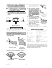
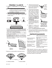
Avoid aiming the control at:
• Objects that change temperature rapidly, such as
heating vents and air conditioners. These heat
sources could cause false triggering.
• Areas where pets or traffi c may trigger the control.
• Nearby large, light-colored objects refl ecting light
may trigger the shut-off feature. Do not point other
lights at the sensor.
60 ft.
(18.3 m)
The control is most sensitive to motion across it.
Motion
Sensor
Motion
❒ Loosen the clamp screw in the
sensor ball joint and gently
rotate the sensor to aim.
❒ Walk through the coverage
area noting where you are
when the lights turn on. Move
the sensor head up, down, or
sideways to change the cover-
age area. Keep the sensor at
least 1" (25 mm) away from
the lamps.
❒ Set SENSITIVITY as needed.
Too much sensitivity may
increase false triggering.
❒ Secure the sensor head into
position by tightening the
clamp screw. Do not over-
tighten the screw.
❒ Set the amount of TIME the
lights stay on after motion is
detected. It is selectable from 1, 5, or 10 minutes.
Bottom of Sensor
ON-TIME
10 5 1 TEST
MIN MAX
SENS
8 ft.
(2.4 m)
110°
❒ Turn the SENSITIVITY (SENS) control to the mid
position and the ON-TIME control to the TEST
position.
Aim Sensor
Down for Short
Coverage
Aim Sensor
Higher for Long
Coverage
Clamp
Ball
Joint
Maximum Range Maximum
Coverage Angle
Least Sensitive Most Sensitive


