


For more information, visit www.desatech.com
5
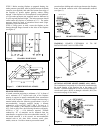
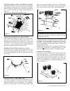
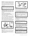
2. Chimney weight above offset rests on return elbow.
Straps must be securely nailed to rafters or joists (see
figure 9, details a & b).
3. Maximum length of pipe between supports (return elbow
or 12S-8DM) is 6’ of angled run. Maximum of two (2) 6’
angled run sections per chimney system (see figure 11).
*For systems with 2 elbow sets, the minimum height is 22 ft.
The maximum height for any system is 50 ft.
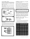
FIRESTOP SPACERS: (V3600FS-8DM)
Firestop spacers are required at each point where the chimney
penetrates a floor space. Their purpose is to establish and
maintain the required clearance between the chimney and the
combustible materials. When the pipe passes through a
framed opening into a living space above, the firestop must be
placed onto the ceiling from below as shown in figure 12.
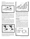
PENETRATING THE ROOF:
To maintain a 1-inch clearance to the pipe on a roof with a
pitch, a rectangular opening must be cut.
STEP 1: Determine the center point through which the pipe
will penetrate the roof.
STEP 2: Determine the center point of the roof. Pitch is the
distance the floor drops over a given span, usually 12 inches.
A 6/12 pitch means that the roof drops 6 inches for each 12
inches one measure horizontally down the roof.
STEP 3: Use the roof-opening chart (figure 13) below to
determine the correct opening length and flashing required.
STEP 4: Remove the shingles around the opening measured
and cut out this section.
STEP 5: Add the next sections of the pipe until the end
penetrates the roofline. Check to see that the proper
clearances are maintained. Extend chimney by adding sections
of double wall pipe until pipe is a minimum of 30 inches
above the highest point of the roof cutout. Termination and
chimney must extend a minimum of 36 inches above the
highest point where it passes through roof.
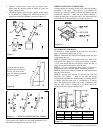
All joints between offset
should be secured with two
screws, only on the outer
pipe, and shall not penetrate
the inner stainless.
Fi
g
ure 10
Figure 9
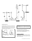
Figure 11 *TYPICAL OFFSET INSTALLATIONS
Figure 12
PITCH SLOPE OPENING "A" MAX USE FLASHING
(degrees) (inches) MODEL NO.
FLAT 0 15 V6F-8DM
0 - 6/12 26.6 16 - 1/8 V6F-8DM
6/12 - 12/12 45.0 20 - 3/8 V12F-8DM
Figure 13