


14
099176
(Pump Rotor, continued)
10.Install blades, pump plate, air filters,
and filter end cover.
11.Replace fan guard and upper shell.
12.Adjust pump pressure (see page 11).
Note:
If rotor is still binding, proceed as
follows.
13.Perform steps 1 through 6 (see page
13).
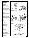
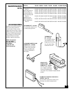
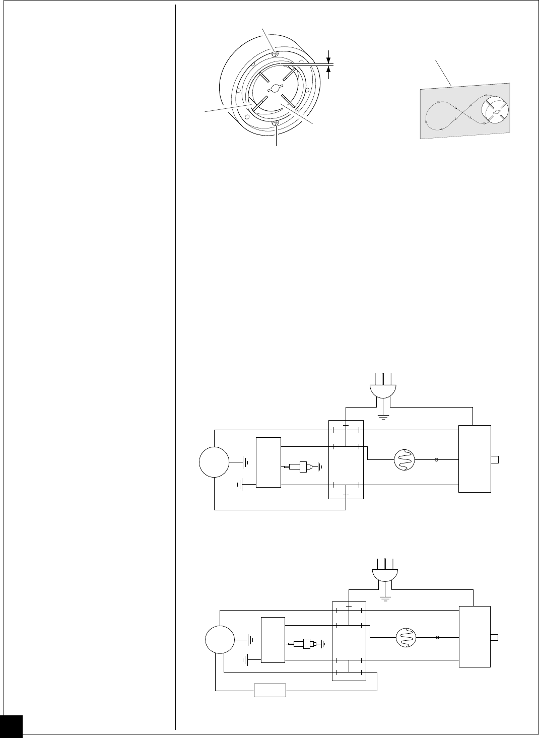
14.Place fine grade sandpaper (600 grit)
on flat surface. Sand rotor lightly in
“figure 8” motion four times (see Fig-
ure 30).
15.Reinstall insert and rotor.
16.Perform steps 10 through 12 above.
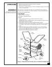
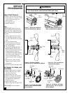
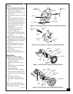
Blade
Rotor
.003"/.004" Gap
Measured With
Feeler Gauge
Gap Adjusting Screw
Sandpaper
Gap Adjusting Screw
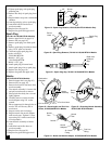
Figure 32 - Wiring Diagram, 70/100/110/150,000 BTU/Hr Models
Figure 30 - Sanding Rotor
Figure 29 - Gap Adjusting Screw Locations
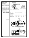
SPECIFICATIONS
Output Rating
(BTU/Hr.)
35,000 50,000 55,000 70,000 100,000 110,000 150,000
Fuel Use Only Kerosene or No. 1 Fuel Oil
Fuel Tank Capacity
(U.S. Gal.) 3.0 4.0 5.0 5.0 9.0 9.0 13.5
Fuel Consumption
(Gal. Per Hr.) .26 .37 .40 .52 .74 .82 1.10
Electric Requirements 120 V/60 Hz (Same All Models)
Amperage
(Normal Run)
2.0 2.0 2.0 2.5 4.5 4.5 4.5
Hot Air Output (CFM) 165 165 175 250 480 490 500
White
Black
Blue
Green
Power Plug
120V 60HZ
Photocell
Spark Plug
Ignitor
Flame
Out
Control
B
Reset
Button
R
Red
Motor
Blue
White
White
White
White
Red
Red
Green
Terminal
Board
Red
Relay
Black
White
Black
Blue
Green
Power Plug
120V 60HZ
Photocell
Spark Plug
Ignitor
Flame
Out
Control
B
Reset
Button
R
Red
Blue
White
White
White
White
Red
Red
Green
Terminal
Board
Motor
Figure 31 - Wiring Diagram, 35/50/55,000 BTU/Hr Models
WIRING
DIAGRAMS