


30
Venting and Combustion Air Installation
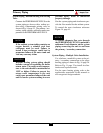
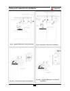
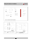
Venting Option - Direct Vent / Vertical
In this vent application the PERFORMANCE
PLUS is vented vertically through the roof or
an unused chimney using the Triangle Tube
Concentric Vertical Vent Kit.
The installer should consider the following
when choosing this vent option:
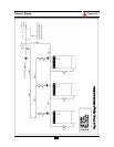
a. The vent system should contain a conden-
sate trap located near the unit as shown in
Fig. 20, page 33.
b. The vent system must pitch back to the unit
1/4 inch per foot as a minimum.
c. The vent system must maintain the follow-
ing clearances to combustibles:
- 0 inches when there are no horizontal
o ffsets and fully enclosed by com-
bustibles on all sides
- 1 inch when there are horizontal offsets
and fully enclosed by combustibles on
all sides.
- 0 inches with or without offsets and
unenclosed or with 1 side open and a
maximum 3 sides enclosed with com-
bustible materials.
- 0 inches with or without offsets and
enclosed with non combustible materials.
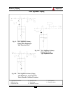
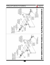
Venting Option - Non-Direct Vent /
Horizontal
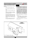
In this vent application the PERFORMANCE
PLUS is vented horizontally through a wall
using only approved 3-inch stainless steel vent
material and using room air for combustion.
The installer should consider the following
when choosing this vent option:
a. The vent system must contain a con-
densate trap located near the unit as
shown in Fig. 21 page 34.
b. The vent system must be pitched a min-
imum 1/4 inch per foot or as specified
by the vent manufacturer.
Although the vent system is allowed to
pitch away from the unit, it is recom-
mended that the vent system pitches
toward the unit with a condensate drain
installed as close to the unit as possible.
Opting to pitch the vent system away
poses potential damage to the building
exterior or to the surrounding landscape
and/or potential risks of icing if conden-
sate is formed.
c. Penetration at the wall requires a wall
thimble.
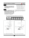
d. Clearance to combustibles must be
maintained per the vent manufacturer’s
requirements. Reference the vent man-
ufacturer’s installation instructions for
additional details.
Maintain a minimum 2-inch clearance to
combustible wall and 1-inch clearance to
non-combustible in the absence of a
manufacturer’s recommended clearance
when penetrating a sidewall.
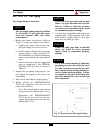
e. At a minimum a 3-inch elbow should
be placed on the combustion air inlet of
the unit. This will prevent an acciden-
tal blockage should anything be placed
on top of the unit.
NOTICE
BEST PRACTICE