20
Primary Piping
SECTION V - Primary Piping
General Piping Requirements
Low Water Cutoff Device
- The PERFORMANCE PLUS is equipped
with a factory installed pressure switch
style Low Water Cut Off device.
- The minimum operating system pressure
allowable with this device is 10 psig.
- Check local codes which require a low
water cutoff device for compliance of
this device.
Backflow Preventer
- Use a backflow preventer valve in the
make-up water supply to the unit as
required by local codes.
Primary System Piping Applications
All piping applications shown in this instal-
lation manual utilize a primary/ secondary
piping arrangement. This method is re c -
ommended as a means to provide priority
to the production of domestic hot water.
F o r o t h e r piping arrangements, consult the
Engineering Department at Triangle Tu b e
o r consult other a p p ro v e d / r e c o g n i z e d
design arrangements.
On piping applications utilizing a single
zone or o t h e r recognized piping design
arrangements it is recommended the
i n s t a l l e r uses flow/check valves with
weighted seats at or n e a r the appliance to
p r event gravity circ u l a t i o n .
To prevent potential outer tank failures the
p r i m a r y system piping must be a “closed”
loop system to avoid any oxygen contami-
nation of the boiler w a t e r.
Expansion Tank and Makeup Water
Ensure the expansion tank is properly sized
for the outer tank volume (20 gallons) and
the system volume and temperature.
Undersized expansion tanks will cause sys-
tem water to be lost through the pre s s u re
relief valve and cause additional makeup
w a t e r to be added to the system. Eventual
p r i m a r y tank failure can result due to this
excessive makeup water a d d i t i o n .
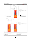
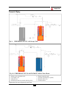
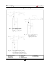
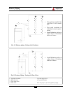
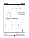
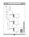
The expansion tank must be located as
shown in Figure 11, 11A or 11B page 23 or
as per recognized design methods. Refer to
the expansion tank manufacturer instruc-
tions for additional installation details.
Connect the expansion tank to an air sepa-
rator only if the air separator is located on
the suction side (inlet) of the system circu-
lator. Always locate and install the system
fill connection at the same location as the
expansion tank connection to the system.
Diaphragm (Bladder) Expansion Tank
Always install an automatic air vent on the
top of the air separator to remove residual
air from the system.
Closed-Type (Standard) Expansion Tank
It is recommended to pitch any horizontal
piping toward the expansion tank 1 inch per
5 feet of piping. Use 3/4” piping for the
expansion tank to allow air within the sys-
tem to rise.
CAUTION
NOTICE
BEST PRACTICE
BEST PRACTICE


