Specifications
68
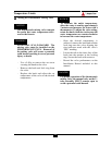
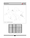
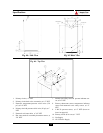
Fig. 45: Rear View
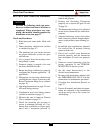
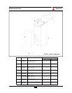
Fig. 44: Side View
1. Primary circuit, ø 1” NPT
2. Primary circuit drain valve connection, ø 1/2” NPT
3. Domestic temperature/pressure relief valve (150
psi), ø 3/4” NPT
4. Primary circuit & pressure relief valve (30 psi), ø 1”
NPT
5. Domestic cold water inlet, ø 3/4” NPT
6. Hot water outlet & secondary thermostat sensor, ø
3/4” NPT
7 . Manual reset safety sensor & pressure indicator sen-
s o r, ø 3/4” NPT
8. Primary thermostat sensor, temperature indicator
sensor and automatic reset safety sensor, ø 1/2”
NPT
9. L.W.C.O. pressure sensor, ø 1/2” NPT (shown as
item 6 on page 66)
10. Primary circuit & air vent, ø 1” NPT
11. Gas Supply
12. 120 V Electric Supply
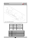
Fig. 46: Top View


