


Dayton Operating Instructions and Parts Manual
8
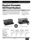
Dayton Portable
Oil-Fired Heaters
®
111166-01A
2E510F, 2E511F, 3E218F, and 3E219F
Maintenance (Continued)
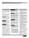
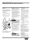
IGNITOR
1. Remove upper shell and fan guard
(See page 6).
2. Remove fan (See page 6).
3. Remove 4 side cover screws with a
5/16" nut driver. Remove side cover
(See Figures 14 and 15).
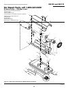
4. Disconnect yellow ignitor wires
from ignition control assembly (See
Figure 16). Pull the ignitor wires up
through the hole in the lower shell.
5. Disconnect fuel line hose and air
line hose. Remove photocell from
photocell bracket (See Figure 16).
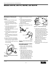
Combustion
Chamber
Photocell
Bracket
Photocell
Assembly
Air
Line
Hose
Fuel
Line
Hose
Ignitor
Wires
Ignitor
Nozzle
Adapter
Bracket
Ignition
Control
Assembly
Side Cover
Figure 16 - Disconnecting Ignitor Wires
from Ignition Control Assembly
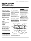
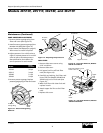
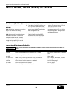
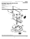
Combustion
Chamber
Photocell
Bracket
Ignitor
Ignitor Screw/Washer
Assembly
Nozzle
Adapter
Bracket
Nozzle Adapter
Bracket Opening
Ignitor
Element
Figure 17 - Ignitor Replacement
6. Remove combustion chamber.
Stand combustion chamber on end
with nozzle adapter bracket on top
(See Figure 17).
7. Remove ignitor screw with a 1/4"
nut driver. Carefully remove ignitor
from nozzle adapter bracket.
8. Carefully remove replacement
ignitor from styrofoam packing.
9. Carefully guide ignitor into
opening in nozzle adapter bracket.
Do not strike ignitor element.
Attach ignitor to nozzle adapter
bracket with screw using a 1/4" nut
driver (See Figure 17). Torque 8 to
15 in. lbs. Do not over torque.
10. Replace combustion chamber.
Do not bend or
strike ignitor
element. Handle with care.
11. Route the ignitor wires back down
through the hole in the lower shell.
Connect wires to the ignition
control assembly.
12. Replace side cover (See Figures 14
and 15).
13. Connect and route fuel line hose
and air line hose to nozzle adapter
assembly (see Fuel and Air Line
Replacement and Proper Routing,
page 9).
14. Replace photocell in photocell
bracket. Route wires as shown in
Figure 18 or 19.
15. Replace fan (See page 6).
16. Replace fan guard and upper shell
(See page 6).
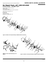
Figure 18 - Removing Air and Fuel Line
Hoses (2E510F and 2E511F Btu/Hr Models
Only)
Fuel Line
Hose
Combustion
Chamber
Nozzle/
Adapter
Assembly
Air Line
Hose
Photocell
Bracket
Burner
Strap
Figure 19 - Removing Air and Fuel Line
Hoses (3E218F and 3E219F Btu/Hr Models
Only)
Fuel Line
Hose
Combustion
Chamber
Nozzle/
Adapter
Assembly
Air Line
Hose
Photocell
Bracket
Burner
Strap