


Dayton Operating Instructions and Parts Manual
10
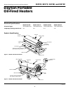
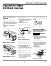
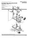
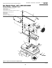
Dayton Portable
Oil-Fired Heaters
®
111166-01A
2E510F, 2E511F, 3E218F, and 3E219F
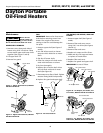
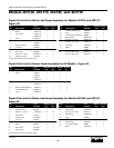
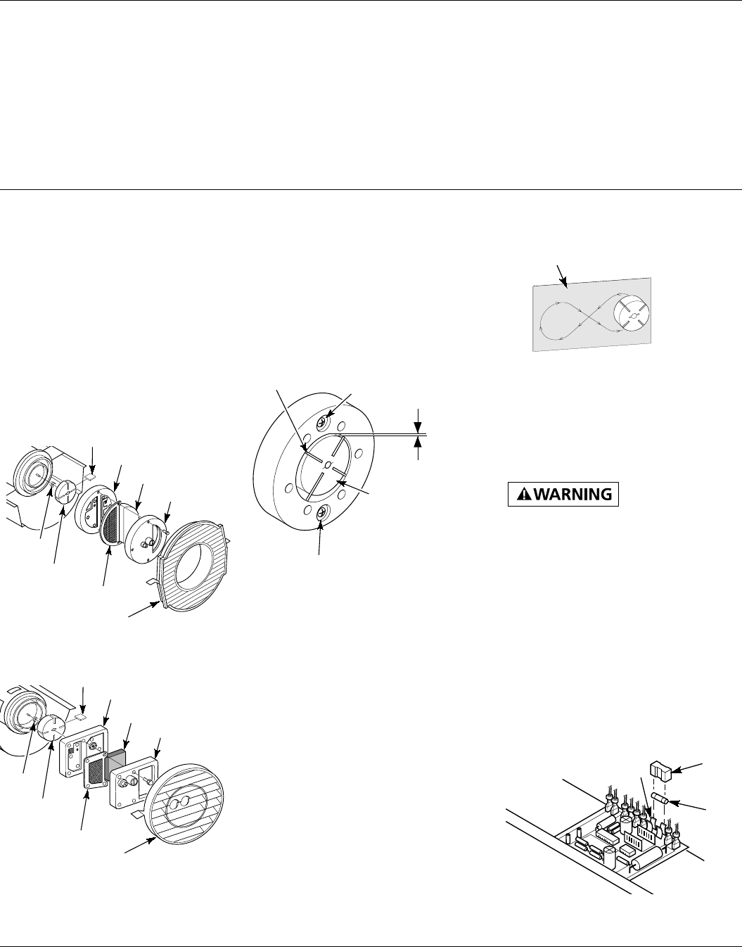
Figure 25 - Gap Adjusting Screw
Locations
Maintenance (Continued)
5. Remove pump plate.
6. Remove rotor, insert, and blades.
7. Check for debris in pump. If debris
is found, blow out with com-
pressed air.
8. Install insert and rotor.
9. Check gap on rotor. Adjust to
.003"/.004" if needed (See Figure 25).
.003"/.004"
Gap
Measured
With
Feeler
Gauge
Blade
Rotor
Gap Adjusting Screw
Gap Adjusting Screw
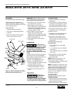
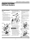
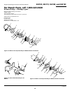
Figure 24 - Rotor Location, Models
3E218F and 3E219F
O
R-Domestic PFA/P 059A
Blade
Pump Plate
Air Intake Filter
Filter End Cover
Insert
Rotor
Air Output Filter
O
TOR-Domestic
PFA/P 056B
Pump Plate
Blade
Air Intake Filter
Filter End Cover
Insert
Rotor
Air Output Filter
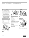
Figure 23 - Rotor Location, Models
2E510F and 2E511F
PUMP ROTOR
(Procedure if rotor is binding)
1. Remove upper shell (See page 6).
2. Remove filter end cover screws using
5/16" nut-driver (See Figures 23 and
24).
3. Remove filter end cover and air
filters.
4. Remove pump plate screws using
5/16" nut-driver.
Fan Guard
Fan Guard
10. Install blades, pump plate, air
filters, and filter end cover.
11. Replace fan guard and upper shell.
12. Adjust pump pressure (See page 7).
NOTE: If rotor is still binding, proceed
as follows.
13. Perform steps 1 through 6 above.
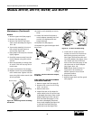
14. Place fine grade sandpaper (600
grit) on flat surface. Sand rotor
lightly in “figure 8” motion four
times (See Figure 26).
Sandpaper
Figure 26 - Sanding Rotor
15. Reinstall insert and rotor.
16. Perform previous steps 10 through 12.
IGNITION CONTROL ASSEMBLY
(PROCEDURE FOR REPLACING FUSE ON
MODELS 3E218F AND 3E219F)
High Voltage!
Figure 27 - Replacing Fuse
Fuse
Fuse
Cover
Fuse
Clips
1. Unplug heater.
2. Remove side cover screws (4) using
5/16" nut-driver to expose ignition
control assembly.
3. Remove fuse cover.
4. Remove fuse from fuse clips.
5. Replace fuse with fuse of the same
type and rating (GMA-10). Do not
substitute a fuse with a higher
current rating.
6. Replace fuse cover.
7. Replace side cover.
NOTE: Rotate rotor one full turn to
insure the gap is .003"/.004" at
tightest position. Adjust if needed.