


Dayton Operating Instructions and Parts Manual 3VG78
4
®
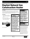
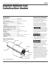
Dayton Natural Gas
Construction Heater
Theory of Operation
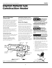
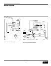
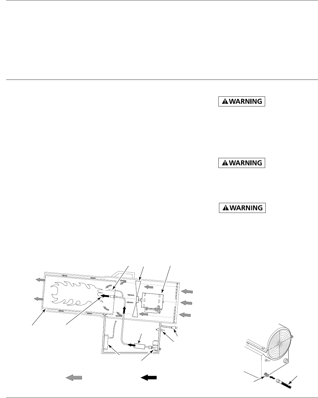
Figure 3 - Cross Section Operational View
Natural Gas Supply
The user must furnish the natural gas
supply and the connections to the heater.
Regulate the natural gas supply from a
minimum 5 inches water column to a
maximum of 1/2 psi. The natural gas
supply capacity should be able to supply a
minimum of 150 cubic feet of gas pressure
for each heater connected to the system.
Consult your natural gas supplier for proper
sizing of the natural gas supply lines.
Follow all local ordinances to codes. In the
absence of local ordinances and codes,
refer to the National Fuel Gas Code
Handbook NFPA54/ANSI Z223.1 and the
Natural Gas Installation Code, CAN/CGA
B149.1.
Installation
Review and
understand the
warnings in the Safety Information
section, pages 2 and 3. They are
needed to safely operate this heater.
Follow all local codes when using this
heater.
Test all gas piping
and connections for
leaks after installing or servicing. Never
use an open flame to check for a leak.
Apply a mixture of liquid soap and
water to all joints. Bubbles forming
show a leak. Correct all leaks at once.
1. Provide natural gas supply system (See
Natural Gas Supply).
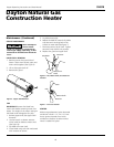
2. Install plumbing to a low pressure
natural gas source. The source must be
regulated to a maximum 1/2 psi. The
plumbing must be a minimum 3/4 inch
i.d. hose or flexible connector not over
10 feet long.
3. Connect hose to heater at the 1/2 inch
SAE flare fitting at the inlet.
THE FUEL SYSTEM
The gas supply attaches to the heater by a
minimum 3/4 inch i.d. hose or flexible
connector. User must supply hose or
flexible connector. The length should be
no more than 10 feet long. The natural
gas moves through the solenoid valve and
the internal regulator and out the nozzle.
THE AIR SYSTEM
The motor turns the fan. The fan pushes
air into and around the combustion
chamber. This air is heated and provides a
stream of clean, hot air.
THE IGNITION SYSTEM
The direct spark ignition system (DSI) sends
voltage to the ignitor, which ignites the
fuel and air mixture.
THE SAFETY CONTROL SYSTEM
This system causes the heater to shut
down if the flame goes out.
Air For Combustion
And Heating
Fuel
Combustion
Chamber
DSI
Ignitor
Clean
Heated
Air Out
(Front)
Fan
Solenoid
Valve
Nozzle
Motor
Power Cord
Internal
Regulator
On/Off Switch
TEMPERATURE CONTROL SYSTEM
Built-in thermostat allows heater to cycle
on and off to maintain consistent area
temperature.
Ventilation
Provide at least a
three-square-foot
opening of fresh, outside air while
running heater. If proper fresh,
outside air ventilation is not provided,
carbon monoxide poisoning can occur.
Provide proper fresh, outside air
ventilation before running heater.
Hose
1/2" Inlet Connector
Figure 4 - Hose and Inlet Connector