


!
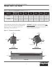
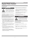
CLEARANCE TO COMBUSTIBLES
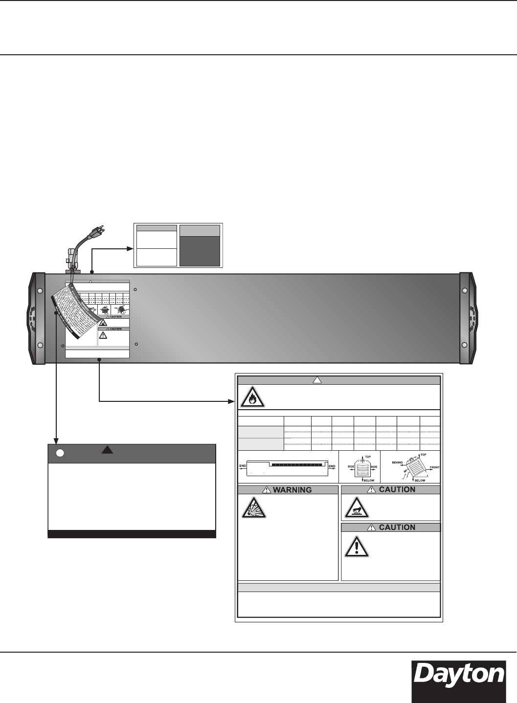
FIRE HAZARD. Always maintain published clearance to combustibles.
In locations used for the storage of combustible materials, signs must be
posted. Consult manual for additional guidelines.
MODEL NO.
DANGER
SIDE(S) BELOW TOP BEHINDEND(S) FRONT
ALL MODELS
(in millimeters)
MOUNTING
ANGLE
0°
0°
30°
30°
22”
559mm
22”
559mm
14”
356mm
N/A
N/A
46”
1168mm
46”
1168mm
13”
330mm
17”
432mm
N/A
N/A
8”
203mm
N/A
N/A
46”
1168mm
ALL MODELS
(in inches)
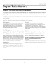
Contact may cause burn.
Do NOT touch hot surface.
Allow to cool before
servicing.
This heater must be installed
by qualified personnel only
and in accordance with the
latest edition of the
ANSI/NFPA Standards.
(ANSI/NFPA 88A Parking Structures), 88B
(Repair Garages), 409 (Aircraft Hangars).
Observe all country, state and local codes.
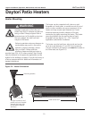
LIGHTING INSTRUCTIONS
1. Rotate heater’s valve knob to “ON” position.
2. Close electrical circuit (usually thermostat).
3. If the heater fails to light, turn “OFF” gas, open electrical circuit and wait 5 minutes
before repeating.
Avoid Serious Injury or
Death. Improper installation,
adjustment, alteration, service
or maintenance can cause
property damage, injury or
death. Read the installation, operation and
maintenance manual thoroughly before
installing or servicing this equipment.
This is not an explosion-proof heater. Where
there is the possibility of flammable vapors or
dusts, consult the local fire marshal, fire
insurance carrier or other authorities for
approval of the proposed installation. Always
maintain minimum ventilation requirements.
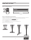
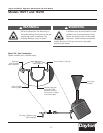
30°
This side down
END VIEWSIDE VIEW
0° Mounting
END VIEW
30° Mounting
The minimum end clearance is 22” or 559mm.
!
CLEARANCE TO COMBUSTIBLES
FIRE HAZARD. Always maintain published clearance to combustibles.
In locations used for the storage of combustible materials, signs must be
posted. Consult manual for additional guidelines.
MODEL NO.
DANGER
SIDE(S) BELOW TOP BEHINDEND(S) FRONT
ALL MODELS
(in millimeters)
MOUNTING
ANGLE
0°
0°
30°
30°
22”
559mm
22”
559mm
14”
356mm
N/A
N/A
46”
1168mm
46”
1168mm
13”
330mm
17”
432mm
N/A
N/A
8”
203mm
N/A
N/A
46”
1168mm
ALL MODELS
(in inches)
Contact may cause burn.
Do NOT touch hot surface.
Allow to cool before
servicing.
This heater must be installed
by qualified personnel only
and in accordance with the
latest edition of the
ANSI/NFPA Standards.
(ANSI/NFPA 88A Parking Structures), 88B
(Repair Garages), 409 (Aircraft Hangars).
Observe all country, state and local codes.
LIGHTING INSTRUCTIONS
1. Rotate heater’s valve knob to “ON” position.
2. Close electrical circuit (usually thermostat).
3. If the heater fails to light, turn “OFF” gas, open electrical circuit and wait 5 minutes
before repeating.
Avoid Serious Injury or
Death. Improper installation,
adjustment, alteration, service
or maintenance can cause
property damage, injury or
death. Read the installation, operation and
maintenance manual thoroughly before
installing or servicing this equipment.
This is not an explosion-proof heater. Where
there is the possibility of flammable vapors or
dusts, consult the local fire marshal, fire
insurance carrier or other authorities for
approval of the proposed installation. Always
maintain minimum ventilation requirements.
30°
This side down
END VIEWSIDE VIEW
0° Mounting
END VIEW
30° Mounting
The minimum end clearance is 22” or 559mm.
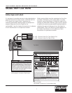
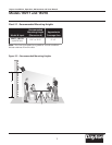
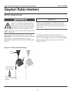
Maintain Clearances to Combustibles to Prevent the Risk of Fire.
Clearances to combustibles must be maintained in order to prevent
the ignition of combustible materials. In locations used for the
storage of combustible materials, signs must be posted to specify the
maximum permissible stacking height to maintain the required
clearances from the heater to the combustibles. Signs must either be
posted adjacent to the heater thermostats or in the absence of such
thermostats in a conspicuous location. Clearances are provided on
the heater’s safety labels and in the heater’s Installation & Operation
Manual. Refer to applicable ANSI or NFPA-54 Standards or local codes
for further information. Post this tag adjacent to the heater’s
thermostat or controls before operating the heater.
WARNING
AVOID SERIOUS INJURY, DEATH OR PROPERTY DAMAGE.
!
INSTALLER. READ AND POST THIS NOTICE.
F/N: LL01 - Clearance Safety Tag
(Affix adjacent to heater’s thermostat).
F/N: LL02 - Observe Proper Gas Type (Natural Gas)
F/N: LL03 - Observe Proper Gas Type (LP Gas)
®
Dayton Installation, Operation, Maintenance and Parts Manual
Models 1RVT7 and 1RVT8
Safety Signs and Labels
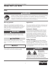
It is important to provide warnings to alert individuals to
potential hazards and safety actions. ANSI Z83.26/CSA
2.37 require you to post a sign “specifying the
maximum permissible stacking height to maintain the
required clearances from the heater to the
combustibles” near the heaters thermostat or in absence
of such thermostats in a conspicuous location.
7
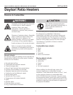
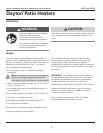
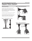
Top Panel
F/N: LLPCL002
Patio Heater Clearance to Combustibles Label
WARNING
OBSERVE
PROPER GAS
DO NOT
ROTATE CONTROL
ASSEMBLY
FOR
GAS TYPE
ONLY
USE TWO
WRENCHES
TO TIGHTEN
Safety warning labels must be maintained on the infra-
red heater. Illustrations of the safety labels, and their
locations, are pictured below. In locations used for the
storage of combustible materials, signs must be posted
to specify the maximum permissible stacking height to
maintain the required clearances from the heater to
combustibles. Signs must either be posted adjacent to
the heater thermostats or in the absence of such
thermostats in a prominent location.