


Dayton Installation, Operation, Maintenance and Parts Manual
Dayton Patio Heaters
®
1RVT7 and 1RVT8
14
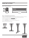
1. Disconnect the power to the heater.
2. Turn off the gas supply to the heater and “bleed”
the gas line.
3. Using two wrenches, slowly loosen the fittings.
Excessive torque on the manifold may misalign the
orifice.
4. Inspect the hose and fittings for abrasion, wear or
damage. Replace if necessary.
To disconnect the gas:
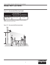
The gas outlet must be in the same room as the
appliance and accessible. It may not be concealed within
or run through any wall, floor or partition.
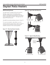
1. Install a sediment trap / drip leg if condensation may
occur at any point of the gas supply line. This will
decrease the possibly of loose scale or dirt in the
supply line entering the heater’s control system and
causing a malfunction. NOTE: High pressure gas
above 14 in. W.C.P. (water column pressure) requires
a high pressure regulator and ball valve (field
supplied).
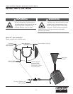
2. A stainless steel flexible hose (field supplied) formed
into a smooth C-shape is recommended. If local
codes prohibit the use of a gas hose, then a swing
joint may be used.
3. Attach the ball valve (field supplied) to the gas
supply pipe. Apply pipe compound to NPT adapter
threads to seal the joint. Use only a pipe compound
resistant to liquid petroleum.
Note: Provide a 1/8 in. NPT plugged tapping
accessible for test gauge connection immediately
upstream of gas connection to the heater (provided
on ball valve, when supplied).
WARNING
!
!
Testing for gas leaks with an open flame
or other sources of ignition may lead to a
fire or explosion and cause serious injury
or death. Test in accordance with NFPA
or local codes.
WARNING
!
!
Failure to install, operate or service
this appliance in the approved manner
may result in property damage, injury
or death. This heater must be installed
and serviced by trained gas installations and service
personnel only.
The installation of this heater must conform with local
building codes or, in the absence of such codes, the
National Fuel Code (NFPA 54).
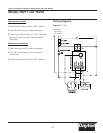
To connect the gas:
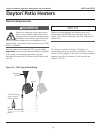
4. Attach the gas connector (field supplied) to the
adapter and the heater’s gas inlet. Seal the joints.
Important! The fittings (nuts) on the flexible
connector (field supplied) must be connected to an
adapter. They may not be directly connected to the
gas supply pipe.
Excessive torque on the manifold may misalign the
orifice. Always use two wrenches to tighten
mating pipe connections.
5. Final assembly must be tested for gas leaks
according to NFPA or local codes.