


®
Dayton Installation, Operation, Maintenance and Parts Manual
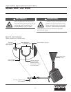
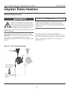
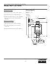
Models 1RVT7 and 1RVT8
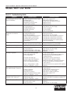
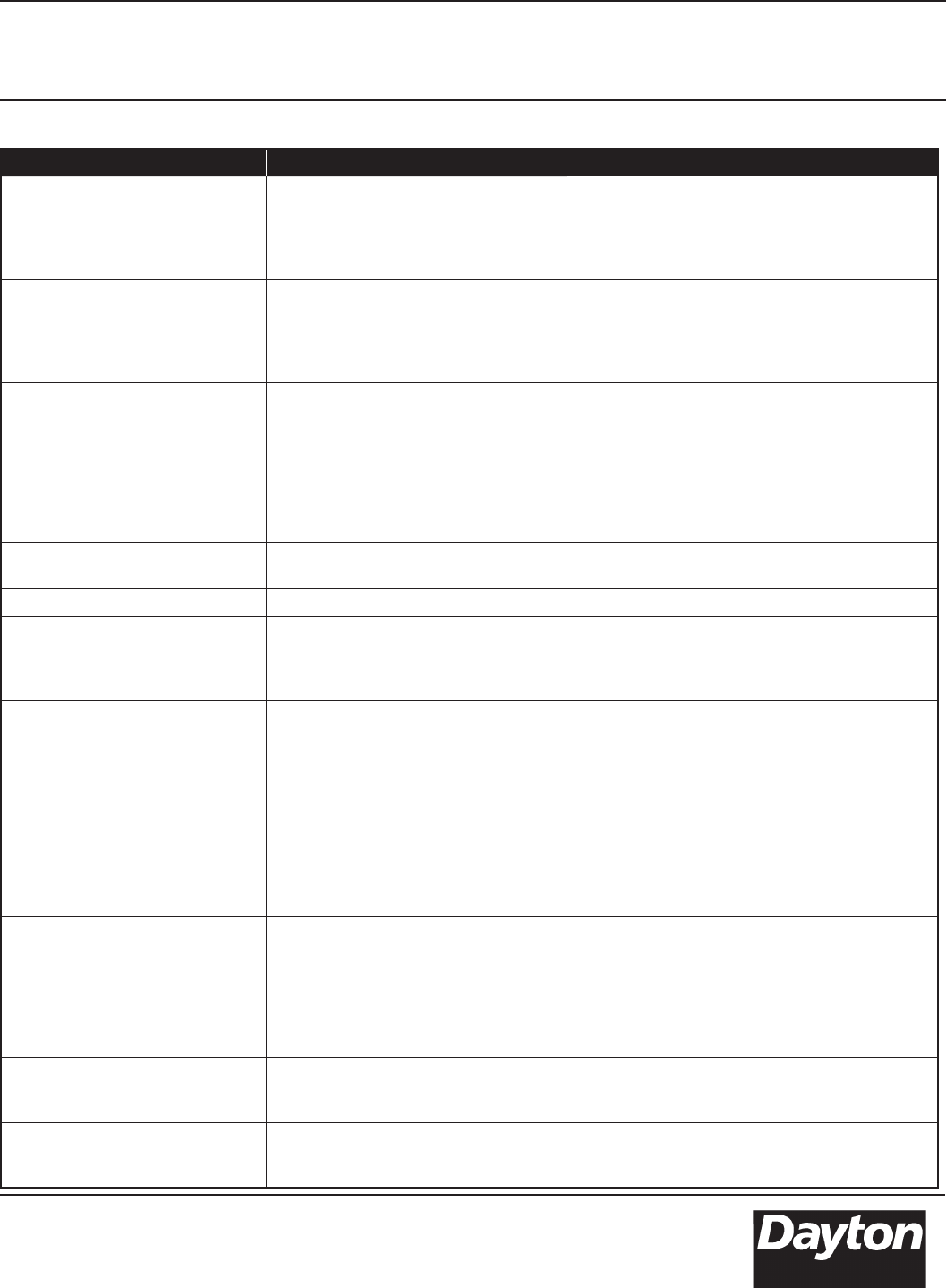
Symptom Possible Cause Corrective Action
Burning of gas-air mixture inside
plenum (flashback).
• Heater mounted at incorrect angle.
• Excessive drafts.
• Gas leaking at orifice.
• Separation of ceramic grids.
• Ceramic grids cracked.
• Mounting angle 0˚- 30˚.
• Relocate or shield from draft.
• Check with leak detector solution.
• Replace burner.
• Replace burner.
Delayed ignition. • Electrode out of specification.
• Low gas pressure.
• Partially blocked orifice.
• Improper orifice size.
• Incorrect gas.
• See ignition system insert.
• See Section 2.0, Gas Supply.
• Clean or replace.
• Consult Dealer.
• See unit nameplate.
Low ceramic surface
temperature or excessive
rollout.
• Dirty or plugged burner ceramics.
• Partially blocked orifice.
• Low inlet gas pressure.
• High or low manifold gas pressure.
• Foreign matter in venturi tube.
• Excessive dark spots on burner.
• Gas supply piping too small.
• Incorrect gas.
• See periodic maintenance instructions.
• Remove and clean.
• See Section 2.0, Gas Supply.
• Adjust main valve regulator as specified.
• See periodic maintenance instructions.
• See periodic maintenance instructions.
• Increase inlet pressure or replace piping.
• See unit nameplate.
Control system overheating. • Heater not mounted correctly.
• Heater mounted too close to ceiling.
• Mounting angle 0˚- 30˚. Level left to right.
• Observe clearance to combustibles.
Gas odor. • Loose pipe connection. • Check connections. Tighten as necessary.
Heater cycles repeatedly. • Heater located in drafty area.
• Low gas pressure.
• Thermostat located in drafty area.
• Defective electrode or circuit board.
• Relocate or shield from draft.
• See Section 2.0, Gas Supply.
• Relocate thermostat.
• Replace.
No spark; no ignition. • Lack of 120V incoming voltage.
• Open high voltage wire.
• Fan not operating.
• Improper electrode gap.
• Loose or open wire connection.
• Pressure switch not satisfied.
• Poor or no equipment ground.
• Unit in “safety lockout” mode.
• Defective “gaslighter” control.
• Check power supply.
• Isolate an ohm for resistance, replace if 0.
• Locate source of electrical problem or
replace faulty fan.
• See Ignition System specifications.
• Check all wires, tighten or replace.
• Verify fan operation. Remove obstructions.
• Check all connections, provide positive
earth ground.
• Interrupt power source, repeat trial for ignition.
• Replace.
Heater lights, and “locks out”
after approximately 10 seconds.
• Poor or no equipment ground.
• Polarity is reversed.
• Low gas pressure.
• Electrode not sensing.
• Heater mounted at incorrect angle.
• Defective “gaslighter” control.
• Check all connections, provide positive
earth ground.
• 120V to black, neutral to white.
• See Section 2.0, Gas Supply.
• Relocate or replace if defective.
• Mounting angle 0˚- 30˚.
• Replace.
Spark is present. No main gas
operation. Unit “locks out”.
• Gas valve in “OFF” position.
• Defective gas valve.
• Defective “gaslighter” control.
• Turn to “ON” position.
• Isolate and check for resistance, replace if 0.
• Replace.
Heater will not shut off. •Defective thermostat or wiring.
• Gas valve stuck or open.
• High gas pressure.
• Replace or repair.
• Replace.
• See Section 2.0, Gas Supply.
Chart 4.1 - Troubleshooting Guide
21