


Heater Operating Instructions
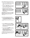
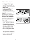
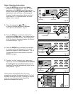
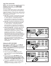
1) Press the MODE key until the word Heat is
displayed in the LCD window. Fig. 20. Each
depression of the MODE key will advance to a
different mode setting
(Cool-Dry-Heat-Fan). The
red indicator light will come on indicating the
“Heating” mode is operational (there may be a
slight delay of 5-10 seconds before the cycle
begins, this is normal).
2) Press the appropriate or key
to select a suitable temperature between
17°C (63°F) to 30°C (88°F).
Fig. 21.
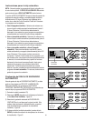
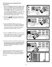
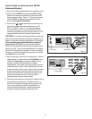
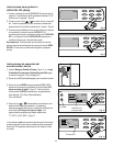
3) Press the FAN key to select the desired fan
speed setting (High-Low). Your selection will be
displayed in the LCD window. Each depression
of the fan key will alternate between the different
fan speed settings. Fig. 22.
4) Press the
SWING key to activate the automatic
air swing (oscillating) feature, (the “air swing”
symbol will appear in the LCD window). Fig. 23.
To deactivate the air swing feature, press the
SWING key again.
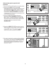
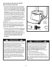
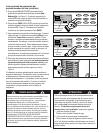
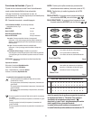
5)
T
o adjust “air flow” direction, (up / down only)
adjust any one of the
Horizontal Louver Blades
(excluding the top or bottom louver)
and the
remaining louvers will automatically adjust to the
same position. Fig. 24.
Heating stops automatically when the room
temperature reaches the desired setting. The “red”
indicator mode light will close. Heating will resume
when the room temperature falls below the
established temperature setting.
13
Water Full
C
ool/Heat/Dry
I/O MODE
S
WING TIMER
CLOCK
FAN
1
2:00
T
IMER
T
EMP.
O
N
MODE HEAT
F
AN SPEED HIGH
00
ON
O
FF
TEMP./CLOCK
A
DJ.
Fig. 20
Red Light Heat Mode
Water Full
Cool/Heat/Dry
I/O MODE
SWING
TIMER
CLOCK
FAN
12:00
TIMER
TEMP.SWING
ON
MODE HEAT
FAN SPEED HIGH
25¡c
ON
OFF
T
EMP./CLOCK
A
DJ.
Fig. 23
Water Full
C
ool/Heat/Dry
I/O MODE
SWING
TIMER
CLOCK
F
AN
12:00
TIMER
TEMP.
ON
MODE HEAT
FAN SPEED HIGH
25¡c
ON
OFF
T
EMP./CLOCK
A
DJ.
Fig. 22
Water Full
C
ool/Heat/Dry
I/O MODE
SWING
TIMER
CLOCK
FAN
12:00
T
IMER ON
TIMER
TEMP.
MODE HEAT
FAN SPEED HIGH
25¡c
ON
O
FF
T
EMP./CLOCK
A
DJ.
Fig. 21
Temperature
Fan Speed
R
W
ater
F
ul
l
I/O
M
ODE
TIM
ER
SWING
TEM
P.
CLOCK
FAN
C
ool
/H
eat/D
r
y
Fig. 24
Air Swing