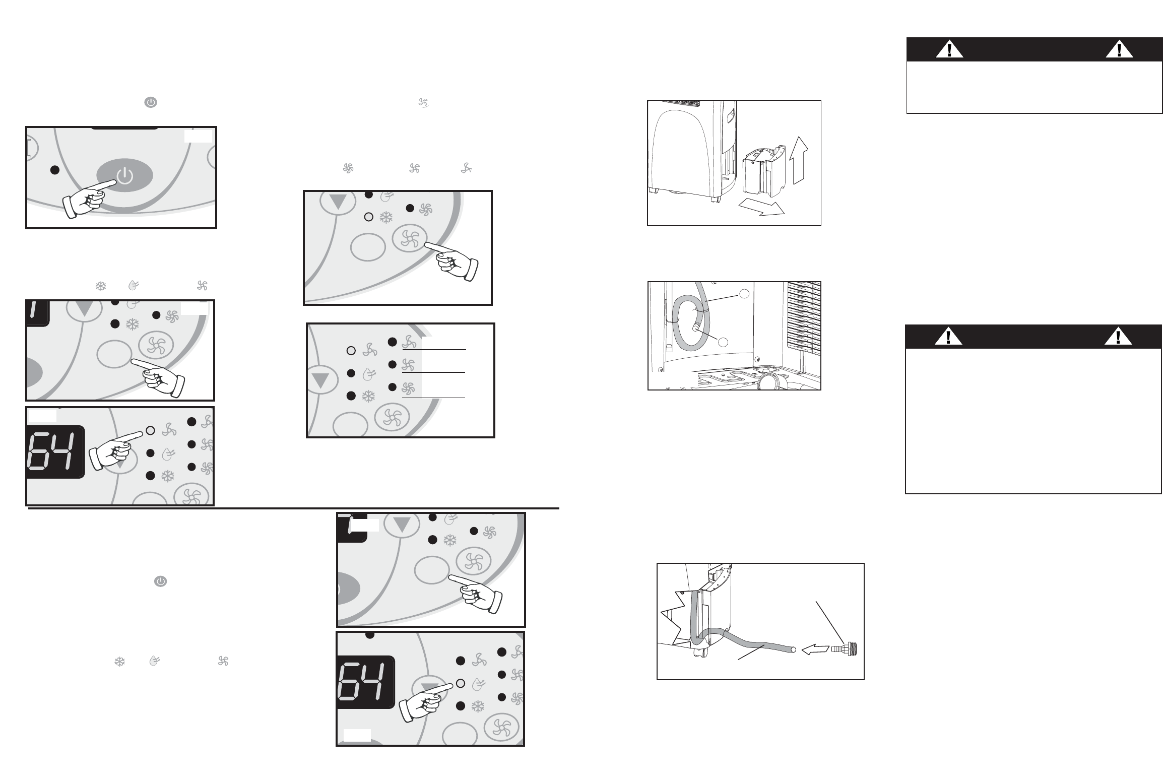
Directives d’utilisation du ventilateur :
REMARQUE : L’installation du tuyau flexible pour
l’échappement d’air n’est pas requise pour le
fonctionnement en mode de ventilation seulement.
1.Appuyer sur la touche INTERRUPTEUR pour
activer l’unité
Fig G
.
2.Appuyer sur la touche MODE
Fig H
jusqu’à
l’affichage du symbole Ventilateur sur le panneau de
commande
Fig I
. Chaque dépression sur la touche
MODE avancera l’affichage à un réglage de mode
différent
(Frais -
Sec
-Ventilateur ).
3.Appuyer sur la touche VENTILATEUR
Fig J
pour
choisir la VITESSE DE VENTILATEUR désirée. Votre
réglage apparaîtra sur le panneau de commande
Fig K
.
Chaque dépression sur la touche VENTILATEUR
avancera l’affichage à un réglage de vitesse différente
(Haute -Moyenne -Basse ).
Directives d’utilisation
Déshumidificateur
:
REMARQUE : L’installation du tuyau flexible pour
l’échappement d’air n’est pas requise pour le
fonctionnement en mode de
Déshumidification
.
1)
Appuyer sur la touche INTERRUPTEUR pour
activer l’unité
Fig G
.
2. Appuyer sur la touche MODE
Fig L j
usqu’à l’affichage
du symbole
Déshumidification
sur le panneau de
commande
Fig M
. Chaque dépression sur la touche
MODE avancera l’affichage à un réglage de mode
différent
(Frais -
Sec
-Ventilateur ).
Important : Il n'y a aucun ajustement pour la vitesse du
ventilateur ou la température pendant le mode de
déshumidificateur. La vitesse de ventilateur est pré-réglée
(haute) et le déshumidificateur fonctionne sans interruption
indépendamment des niveaux ambiants d'humidité ou
réglage du température.
22
M
MODE
MODE
Fig G
Fig H
MODE
Haute
Moyenne
Basse
Fig J
Fig K
CF
MODE
Fig I
MODE
CF
MODE
Fig M
Fig L
Direct Drain Instructions
1. Remove the internal water tank; gently lift then
pull outward as shown in Figure 2.
2. Locate the direct drain hose Figure 3 (a), and
proceed to remove the black plug located at the
end of the hose Figure 3 (b).
3. Route the end of the hose under the side of the
water tank, then through the hole provided on the
face of the tank and place the water tank back
into the cabinet (As shown in Figure 4).
If
required
, attach the included drain hose adapter
(Fig 4) to the end of the drain tube and attach a
section of garden hose (not included) to suit your
continuous drain option requirements.
Important:
Ensure that the drain hose section
does not interfere with the correct positioning of
the water tank inside the cabinet.
Please Note: Remember to reverse the above direct
drain instructions when relocating the unit to a
location where continuous drain is not possible.
Failure to replace and recap the direct drain hose
may resulting in flooding of the immediate area.
a
b
Fig.3
1
2
Fig.2
Fig.4
Water Tank Safety Feature
This unit is equipped with a fail-safe switch
mechanism which prevents the unit from condensing
water in the event the internal water tank is
accidentally displaced and/or is full. If this situation
occurs, the (RED) WATER FULL indicator light will
illuminate. This condition will remain steady until the
external water tank is emptied.
NOTE: No cooling will occur until the internal
tank is emptied and/or re-positioned. It may take
several minutes before the compressor resumes
normal operation.
CAUTION
During air conditioning and dehumidifier mode, if the
compressor cycle is interrupted (water full condition,
unplugged, power failure,etc.) and reinstated
immediately thereafter, (within 3-5 minutes) a
“compressor protection circuit” is automatically
activated. The compressor cannot operate during
“compressor protection” mode. (this is normal) It may
take 3-5 minutes before the “protection circuit” self-
deactivates.
DO NOT ATTEMPT TO START THE UNIT
(COMPRESSOR) DURING THIS PERIOD.
5
CAUTION
Always empty the external water tank before
attempting to move or re-locate the unit to another
location.
Direct Drain
Adapter
Direct Drain Tube


