


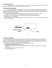
GREEN
CHANNEL 2
RED: +12 BATTERY
OUTSIDE
EMERGENCY
RELEASE SWITCH
DRIVER'S DOOR MOTOR
(PDR-1 shown)
+12 BATTERY
RED
FUSE
BROWN
CHANNEL 1
GROUND
GROUND
GREEN
BLUE
SPLICE
SPLICE
BLACK
These channels
must be connected
to relays if they are
used.
YELLOW: IGNITION
safety disable
BLACK: GROUND
PURPLE
BROWN
WHITE/BLACK
BLUE
CHANNEL 4
CHANNEL 5
CHANNEL 7
CHANNEL 6
ORANGE:
CHANNEL 3
WHITE
RED
TO CHANNEL 3
ACUTATOR
DO NOT USE
+12 BATTERY
BLUE
GREEN
ANTENNA,
DO NOT GROUND
DAKOTA DIGITAL
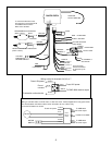
To reverse the direction of the
door actuators, reverse the BLUE
and GREEN wires from the
PDR-1 door actuators.
PASSENGER'S DOOR MOTOR
(PDR-1 shown)
YELLOW
BLUE
not used
not used
+12V
CH 1
CH 2
FUSE
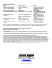
To CMD-4000 channel output.
Fused 12V power.
Do not
connect.
Fused 12V power.
To solenoid or other device.
Wiring a relay for channels 3,4,5,6, or 7
87
BLACK
BLUE
86
85
30
GREEN
RED
WHITE
4
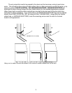
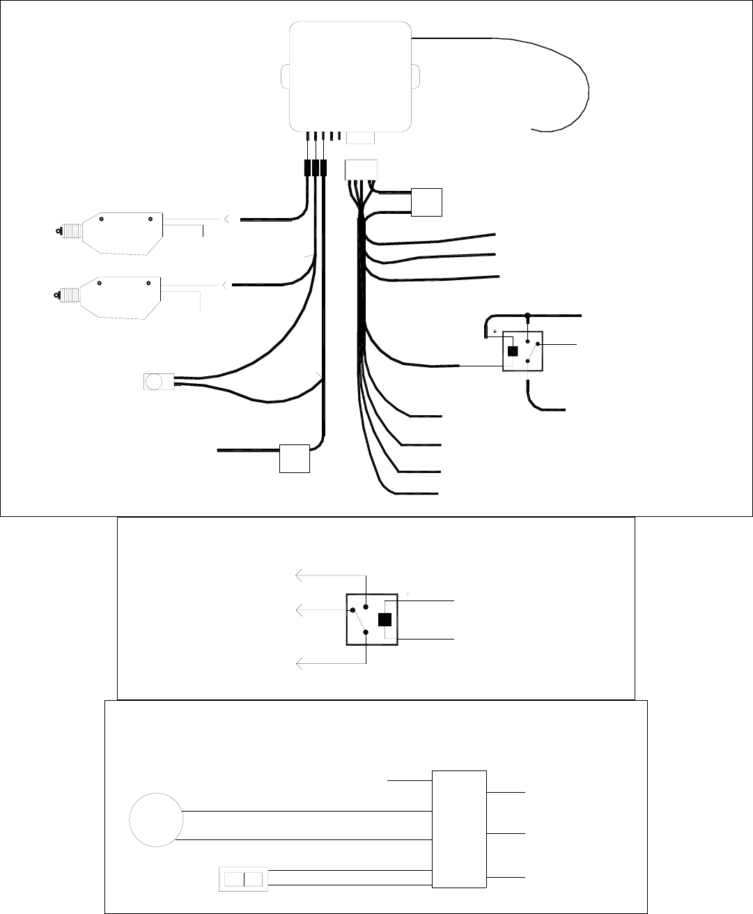
Wiring to a window motor, trunk lift motor, or door lock motor. Dakota Digital RLY-2 relay pack shown.
To CMD-4000
Channel output.
To CMD-4000
Channel output.
FUSED 12V POWER
The wires between the switch and the motor will need to be cut, and the relay
pack wired in between as shown.
Fused 12V power.
MOTOR
MOTOR
SWITCH
PURPLE
GREEN
BROWN
WHITE
BLUE
RELAY
RED
small wire
GREEN
PACK
BLUE
small wire
DUAL