


2
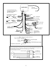
WIRING HARNESS COLOR CODE.
10 pin connector
RED constant 12 volt battery source
BLACK chassis ground
YELLOW ignition key switched 12 volts
VIOLET CHANNEL 7 relay (optional)
WHITE/BLACK CHANNEL 6 relay (optional)
BLUE CHANNEL 5 relay (optional)
BROWN CHANNEL 4 relay (optional)
ORANGE CHANNEL 3 relay (optional)
GRAY not used
GREEN not used
5 spade connectors
5
th
from end VIOLET not used
4
th
from end ORANGE not used
3
rd
from end RED +12 volt battery source
2
nd
from end BROWN driver’s door latch actuator (CHANNEL 1)
outside end YELLOW passenger’s door latch actuator (CHANNEL 2)
The Brown and Yellow wires on the spade connectors are connected to internal relays and can
feed 12 volts out at up to 30 amps. The orange, white/black, blue, brown, and orange wires are
negative switched outputs designed to turn on external relays. These outputs can only handle 0.25
amps and must be used with a relay. Two additional relays are supplied in the kit. To use all 7
channels you will need to purchase three additional relays.
OPERATION
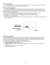
Each key chain transmitter has four buttons. Each button will activate its own independent
channel when pressed. Also, an additional 3 channels can be activated by pressing button 1 and one
of the other three buttons at the same time.
• Button 1 activates the driver’s door latch release on Channel 1. Button 2 activates the
passenger’s door latch release on Channel 2. These channels provide 12 volts out which can
feed up to 30 amps. These outputs will remain on for as long as the button is held, so the buttons
should never be held in for more than a couple of seconds at a time to avoid burning out the door
actuators.
• Button 3 can activate an external relay to power a trunk latch release or other function on the
Channel 3 output. Button 4 can activate an external relay on the Channel 4 output.
• Pressing buttons 1 and 2 at the same time activates an external relay on Channel 5.
• Pressing buttons 1 and 3 at the same time activates an external relay on Channel 6.
• Pressing buttons 1 and 4 at the same time activates an external relay on Channel 7 for ½ sec.
When the ignition key is "ON", the remote system outputs for channels 1, 2, 3, and 4 are
disabled. The remote outputs for channels 5, 6, and 7 will operate whether the ignition is on or off.
This safety feature will not allow the doors to accidentally release while the vehicle is in motion. This
disables the key chain transmitters only. The "override" switches will not be disabled.
The unit will stop operating for 30 seconds if any combination of buttons 1 or 2 are pushed
eight (8) times in 30 seconds. This is to prevent overheating the door actuators.
The emergency release switch provides power directly to the door release actuator. The
switch bypasses the remote system, so it will operate when the system is disabled by the ignition
being on.
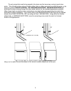
On vehicles with suicide doors, we recommend using a mechanical sliding dead bolt lock to
ensure that there is no way for the doors to open while the vehicle is going down the road.