


11Teflon is a registered trademark of E.I. DuPont
O. APPENDIX FOR BASEMENT INSTALLATIONS
The following variations are generally required for basement
installations:
INSTALL THE DRAIN CONNECTION
For basement installations, the drain saddle is generally
not used. Instead, the RO reject line (SFC tubing) is routed so
that it drains into a laundry sink, floor drain, or standpipe
through an approved air gap.
MOUNT THE FAUCET
If you choose to use the air gap faucet included with the
RO system, follow the faucet installation instructions given ear-
lier in this manual. Do not hook up any air gap tubing to the
faucet since an alternate air gap will be used elsewhere in the
drain line.
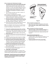
If you choose to use the optional non-air gap faucet, follow
the instructions below.
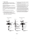
A) Familiarize yourself with all of the components shown in
the diagram of the non-air gap faucet. (See Fig. 2)
B) Install only the chrome base plate and rubber sealing washer
onto the threaded nipple. (Plumbers' putty may be used in
place of the sealing washer for a neater appearance.)
C) Feed the threaded nipple through the sink/countertop
mounting hole (a 9/16" hole is adequate).
D) From underneath the sink/countertop, install the plastic
bottom washer, flat washer, star washer, and hex nut onto
the threaded nipple. Hand tighten the hex nut until the
faucet feels snug.
E) After rechecking the faucet orientation, tighten the hex nut
with at 9/16" wrench until the faucet feels secure.
F) From above the sink, make any minor orientation
corrections by turning the faucet on its "flats" with a
padded adjustable wrench. Use care so as not to mar the
chrome finish.
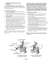
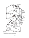
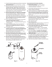
INSTALL THE PURIFICATION ASSEMBLY AND THE
STORAGE TANK
The purification assembly is generally mounted to the base-
ment wall (using wall anchors) or to the wood ceiling supports. To
mount the purification assembly, keep the bracket level and mark
the location of the mounting holes. Install wall anchors and/or
mounting screws as required. Leave the screw heads protruding
to allow the bracket mounting slots to slide over them. (See Fig. 7)
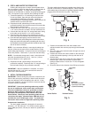
The tank may be oriented either vertically or horizontally and
can be placed on a shelf, on the floor, or suspended from the ceil-
ing supports using brackets.
An effort should be made to minimize the distance between
the tank and purification assembly in order to ensure an adequate
flow rate to the faucet. For horizontal positioning on a shelf or floor,
carefully detach the tank base from the bottom of tank and use it
as a cradle.
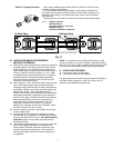
MAKE THE TUBING CONNECTIONS
1) A proper length of the 1/4" orange feed water tubing
should already have been connected to the feed water
tapping valve. Route it through the large opening in the
bottom of the metal bracket and loop it back to the "FEED"
connection on the purification assembly.
2) Thread the taped 3/8" x 1/4" elbow fitting into the tank valve.
Do not over tighten.
3) Connect a longer length of 3/8" blue tubing (not included) to
the faucet adapter. Route the tubing through the floor to the
location of the purification assembly. Remove the existing
3/8” blue tubing from the purification assembly. Route the
other end of the longer length of 3/8” blue tubing through the
large opening in the bottom of the metal bracket and connect
it to the “FAUCET” connection on the purification assembly.
NOTE: Instead of removing the existing 3/8" blue tubing from
the purification assembly, a 3/8" connector fitting can be used
to join the tubing from the faucet with the tubing from the purifi-
cation assembly.
4) Route the 3/8" yellow tubing from the purification assembly
to the storage tank.
5) Route 1/4" tubing from an appropriate drain connection
(e.g. laundry sink, floor drain, standpipe) to the location of
the purification assembly. An air gap must be provided
between the outlet and the drain connection.
6) Connect the red SFC tubing from the purification assembly
to the 14" tubing from the drain connection using the 1/4"
connector fitting on the end of the SFC tubing.