25
XII Service and Maintenance
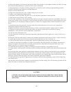
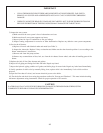
The following procedure should be performed on an annual basis:
1) Turn off electrical power and oil supply to the boiler.
2) Clean the boiler as follows:
a) Remove vent connector and piping.
b) Remove barometric draft regulator.
c) Remove top jacket panel to gain access to boiler flue collector.
d) Unscrew four wing nuts and remove canopy retaining carriage bolts, lift off the canopy and ceramic fiber sealing
strips.
e) Unplug the burner, disconnect the oil lines (if the pump is hard piped), and remove the two 5/16” bolts securing the
burner door. Open the burner swing door.
f) Thoroughly brush boiler flueways from the top and diagonally between casting pin rows. Be careful when brushing
the rear passage not to damage the rear target wall insulation.
g) Vacuum soot and debris from combustion chamber.
h) Check condition of rear target wall insulation, combustion chamber liner, and burner door insulation; replace if
required.
i) Check burner head for signs of deterioration. Clean the head of any deposits.
j) Close burner door, reinstall 5/16” bolts, reconnect fuel oil and electrical lines.
k) Installation of boiler canopy, jacket top panel barometric draft regulator and breeching piping is done in reverse
order of removal. Make sure canopy is sealed tight to the casting; replace ceramic fiber sealing strips as needed. All
vent piping joints must be flue gas leak free and secured with sheet metal screws.
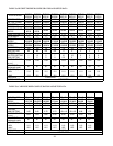
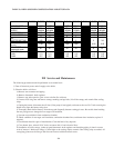
TABLE 3c: RIELLO BURNER CONFIGURATION AND SETUP DATA
24
TWZ065 TWZ075 TWZ100 TWZ090 TWZ125 TWZ150
TWZ120 TWZ175 TWZ200
BURNER MODEL
40F5 40F5 40F5 40F10 40F10 40F10
STANDARD
DEL DEL DEL. DEL HAGO DEL
NOZZLE
0.60/60A 0.85/60W 1.00/60A 1.25/60B
1.35/45B 1.65/45B
PUMP PRESS (psi)
150 150 150 150 150 150
TURBULATOR
02 41
1.5 2
AIR
SHUTTER SETTING
2.60 2.85 4 3
33.8
DRAFT OVER FIRE
(in w.c.)
MAX. SMOKE
(bacharach scale)
FLUE CO2 (%)
MIN.
11.0 11.0 11.0 11.0 11.0 11.0
MAX
12.5 12.5 12.5 12.5 12.5 12.5
-0.02 -0.02 -0.02-0.02 -0.02 -0.02
#1 #1 #1 #1 #1 #1


