10
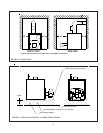
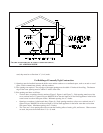
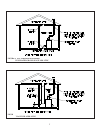
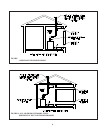
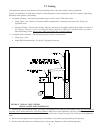
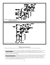
FIGURE 9: TYPICAL VENT SYSTEM
INSTALLATION AND COMPONENTS
VI Venting
Vent installation must be in accordance with local building codes, or the local authority having jurisdiction.
Typical vent installation is illustrated by Figure 9. The components of vent installation are the vent connector (breeching),
barometric draft regulator, and chimney.
1) Acceptable Chimneys - The following chimneys may be used to vent a TWZ series boiler:
• Listed Type L vent - Install in accordance with the manufacturer’s instructions, the terms of its listing, and
applicable codes.
• Masonry Chimney - The masonry chimney must be constructed in accordance with the latest edition of Standard
for Chimneys, Fireplaces, Vents, and Solid Fuel Burning Appliances (NFPA 211) and lined with a clay liner or
other listed lining system.
Do not vent a TWZ series boiler into an unlined chimney.
2) Acceptable Vent Connectors - The following may be used for vent connectors:
• Listed Type L vent.
• Single Wall Galvanized Pipe - Use 0.018” (26 gauge) or heavier.
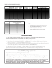
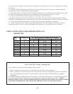
3) Chimney and Vent Connector Sizing - See Table 2 for minimum vent connector and chimney sizing. The vent connector
size must not be smaller than boiler flue collar diameter. Where two or more appliances vent into a common vent, the
cross-sectional area of the common vent should at least equal the area of largest vent plus 50% of the area in the additional
vents.
4) Do not vent this appliance into any portion of a mechanical vent system operating under positive pressure.
5) Do not connect the boiler into a chimney flue serving an open fireplace or other solid fuel appliance.
9


