


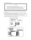
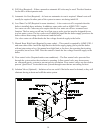

2) Do not use compression ttings in oil piping.
3) Do not use Teon tape in oil piping
4) Do not manifold multiple oil appliances on a two-pipe system. Run dedicated lines for each
appliance back to the tank or use a transfer pump and day tank to get oil to a location where it
can be gravity fed to each appliance.
5) Do not use check valves in gravity feed systems.
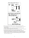
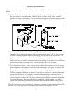
6) Where a new oil tank is to be installed, and where codes permit, the best location for the tank is
in a warm space (such as basement) where a one-pipe gravity system can be used. Such a
location will eliminate problems caused by air-inltration and cold oil.
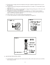
7) Use only #2 fuel oil with physical and chemical characteristics meeting the requirements in
ASTM D-396.
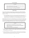
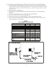
VIII WIRING
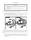
Figure 22 is a connections diagram for the ODV boiler. The following connections must be made in
the eld:
L1 – Line voltage “hot”
L2 – Line voltage “neutral
C1 – Circulator “hot”
C2 – Circulator “neutral”
T, T – 24 volt thermostat connections.
Green Screw in L7248A – Ground connection
This boiler must be wired to a dedicated circuit having a 15-amp fuse or circuit breaker. The minimum
size wire that should be used in this circuit is 14 AWG.
If this boiler is to be used in a multiple zone installation, T, T are generally connected to either zone
valve end switches or a set of dry relay contacts which will start the boiler when any one zone calls for
heat. A separate transformer must be used to power zone valves. If this boiler is to be used in a circulator
zone system, terminals C1 and C2 cannot be used as they will be energized regardless of which zone is
calling for heat.
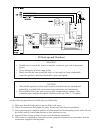
CAUTION
Fuel oil will attack silicone pressure switch tubing. If at all possible, route oil lines
under air inlet collar.
WARNING
All wiring and grounding must be done in accordance with the authority having ju-
risdiction or, in the absence of such requirements, with the National Electrical Code
(ANSI/NFPA 70).
18