


13
2 (contd.)
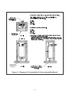
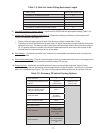
Example: A 60/100mm concentric vent system is planned for a horizontally vented MWC116 which
has the following components:
60/100mm Elbow Adaptor (supplied with the boiler)•
1 ft Straight Pipe•
90 elbow•
Uncut Terminal Section (supplied with the boiler)•
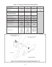
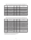
The Vent Option #2 column in Table 7.1 describes a horizontal direct vent system using 60/100mm
concentric vent pipe. From this column, we see that a MWC116 may have a vent length of up to 8ft-
10in. The 60/100 Elbow Adaptor supplied with the boiler is not considered. The length of the terminal
section (not including the plastic terminal itself) is approximately 22 1/2” (1.9ft) installed. From Table
7.5, we see that the equivalent length of the 60/100mm elbow is 4.5ft. The total equivalent length of
the planned venting system is therefore:
1ft (Straight ) + 4.5ft (90 Elbow) + 1.9ft (Uncut Terminal Section) = 7.4ft.
Since Table 7.1 shows a maximum allowable vent length of 8ft-10in, the planned vent system length
is acceptable. Note that the 82mm inlet air orifi ce supplied with the boiler is not used.
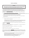
Minimum Vent and Air Intake Lengths 3) - Observe the minimum vent lengths shown in Tables 7.1 and 7.6.
Permitted Terminals for Horizontal Venting:4)
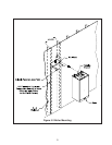
Vent Option 1, 2• - The 60/100mm concentric vent terminal is supplied with the boiler as part of the
standard vent system.
Vent Option 3• - Use the optional 80/125mm Concentric Vent Terminal (Crown PN 230531)
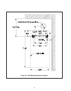
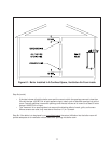
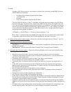
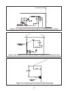
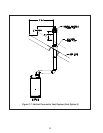
Horizontal Vent Terminal Location5) - Observe the following limitations on the vent terminal location (also
see Figure 7.4).
Vent terminal must be at least 1 foot from any door, window, or gravity inlet into the building.•
The bottom of the terminal must be at least 12” above the normal snow line. In no case should it be •
less than 12” above grade level.
The bottom of the vent terminal must be at least 7 feet above a public walkway. •
Do not install the vent terminal directly over windows or doors.•
The bottom of the vent terminal must be at least 3 feet above any forced air inlet located within 10 •
feet.
In the USA, maintain a clearance of at least 4ft horizontally from the vent terminal to gas meters, •
electric meters, regulators and relief equipment. In Canada, maintain a 6ft clearance between the
vent terminal and these devices.
Do not locate the vent terminal under decks or similar structures.•
Top of vent terminal must be at least 5 feet below eves, soffi ts, or overhangs. Maximum depth of •
overhang is 3 ft.
Vent terminal must be at least 6 feet from an inside corner.•
Vent Terminal must be at least 2ft from adjacent buildings.•
Under certain conditions, water in the fl ue gas may condense, and possibly freeze, on objects around •
the vent terminal including on the structure itself. If these objects are subject to damage by fl ue gas
condensate, they should be moved or protected.
If possible, install the vent and air intake terminals on a wall away from the prevailing wind. Reliable •
operation of this boiler cannot be guaranteed if these terminals are subjected to winds in excess of 40
mph.
Air intake terminal must not terminate in areas that might contain combustion air contaminates, such •
as near swimming pools. See Section IV for
more information on possible contaminates.