


12
VII Venting
WARNING
Failure to vent this boiler in accordance with these instructions could cause fl ue gas to enter
the building resulting in severe property damage, personal injury, or death:
Do not attempt to vent this boiler with galvanized, PVC, or any other vent components not •
listed in Table 7.3.
Do not obtain combustion air from within the building. •
Do not install a barometric damper or drafthood on this boiler.•
A. Vent System Design
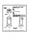
There are two basic ways to vent this boiler:
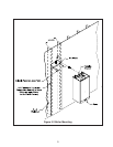
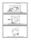
Horizontal (“Side Wall”) Concentric Venting• - Vent system exits the building through an outside
wall. Concentric venting consists of a “pipe within a pipe”. Flue gas exits the building through the inner
pipe and combustion air is drawn into the boiler through the space between the inner and outer pipe.
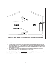
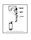
Vertical Concentric Venting - • Vent system exits the building through the roof. Concentric venting
consists of a “pipe within a pipe”. Flue gas exits the building through the inner pipe and combustion
air is drawn into the boiler through the space between the inner and outer pipe.
Both of these systems are considered “direct vent” because in both, combustion is drawn directly from the
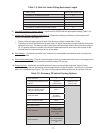
outdoors into the boiler. A description of all of these venting options are shown in Tables 7.1 and 7.6. For
clarity, these vent options are numbered from 1 to 6. One of the vent option columns in Tables 7.1 or 7.6 must
match the planned vent and air intake system exactly. In addition, observe the following guidelines:
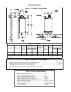
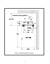
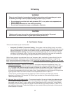
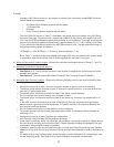
Approved vent systems1) - Use only one Concentric vent system components supplied by Crown. The
standard boiler is supplied with a concentric vent system having a maximum usable length of 25” (Figure
2.1). For longer runs, additional straight lengths and elbows are available from Crown. In some cases,
larger diameter concentric pipe must be used. Each Crown concentric vent component consists of an
inner pipe of polypropylene and the outer pipe of steel. Integral gaskets on each concentric fi tting provide
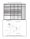
a gas tight seal. A list of all Crown concentric vent components is shown in Table 7.3.
In this manual, concentric pipe sizes are called out in terms of the inner and outer pipe nominal
diameters in millimeters. For example, “60/100mm” pipe consists of a 60mm exhaust pipe inside a
100mm diameter outer pipe.
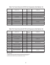
Maximum Vent and Air Intake Lengths2) - The maximum length of the vent air intake piping depends upon
the vent option selected. See Table 7.1 or 7.6 for the maximum vent length. In horizontal vent systems,
the lengths shown in Table 7.1 are in addition to the Elbow Adaptor on top of the boiler. If more elbows
are desired, the maximum allowable vent length must be reduced by the amount shown in Table 7.5 for
each additional elbow used. Termination fi ttings are never counted, although the length of the concentric
terminal section is counted.
CAUTION
Moisture and ice may form on the surfaces around the vent termination. To prevent
deterioration, surfaces should be in good repair (sealed, painted, etc.).