


54
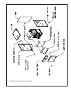
F. Electrical Wiring Connections
(Also refer to wiring diagrams in Part X of the installation manual)
1) A pre-wired limit control (L8148E or L8124E) specific to the control package ordered with the boiler has been provided by the
factory.
2)
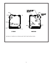
Blocked Vent Switch - Locate the two wires marked “8”. Connect these wires to the terminals on the blocked vent switch (it
does not matter which of these wires is connected to which terminal on the blocked vent switch). Install the strain relief
provided in the hole in the jacket through which these wires pass.
3)
Flame Roll-Out Switch:
a) Route the wire marked “10” through the bushing located on the left jacket panel and connect it to one side of the flame
roll-out switch.
b) Route the wire marked “7” through the bushing located on the left jacket panel and connect it to the other side of the
flame roll-out switch.
4) Standing Pilot Gas Valve (Honeywell VR8200, VR8300 or Robertshaw Model 7000ERHC-S7C) - Connect wire “6” to the “TH”
terminal on the gas valve. Connect wire “5” to the TR terminal on the gas valve.
Note: Boilers equipped with the Robertshaw 7000ERHC are also equipped with a Honeywell Model V8295 gas valve to
provide redundancy. This valve should be factory pre-wired to the 7000ERHC with one black lead connected to the “TH”
terminal and the other black lead connected to the “TR” terminal on the 7000ERHC gas valve.
5) Honeywell Intermittent Ignition System:
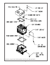
a) Mount the S8600 series ignition control to the left side of the jacket just above the gas manifold using the standoff
bracket supplied and #10 sheet metal screws.
b) Locate the intermittent ignition harness plugged into the gas valve assembly. This harness has red, blue, and yellow
wires and has molex plugs on both ends. Plug the loose end of the harness into the S8600 module.
c) Plug the green burner ground wire numbered “4” to terminal 4 on the S8600. Check that the ground wire has been routed
under the burners and that the other end is attached to the pilot assembly under the lower mounting screw.
d) Plug the red wire with the yellow trace, numbered “5”, to terminal 5 on the S8600 module.
e) Plug the black wire with the white trace, numbered “6”, to terminal 6 on the S8600 module.
f) Plug the orange Pilot Ignition Cable, numbered “9”, to terminal 9 on the S8600 module. Verify that this cable has been
routed under the burners and that the other end is plugged onto the pilot assembly electrode.
G. Complete Installation
Follow the instructions that start on page 1 of this manual to complete boiler installation.
53