


20
IX Wiring
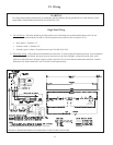
Single Zone Wiring
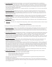
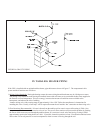
1) 120 Volt Wiring - The boiler should be provided with its own 15A branch circuit with fused disconnect. All 120 volt
connections are made inside the L8148E or L8124E aquastat relay as follows (also see Figures 18-21):
• Hot (“black”) - Terminal “L1”
• Neutral (“white”) - Terminal “L2”
• Ground (“green” or bare) - Ground screw on case of L8148E or L8124E
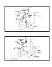
2) Thermostat Wiring - Follow thermostat manufacturer instructions. To insure proper thermostat operation, avoid installation
in areas of poor air circulation, hot spots (near any heat source or in direct sunlight), cold spots (outside walls, walls
adjacent to unheated areas, locations subject to drafts). Provide Class II circuit between thermostat and boiler. Connect
thermostat wire leads to terminals T and TV inside L8148E aquastat relay.
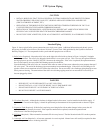
WARNING
All wiring and grounding must be done in accordance with the authority having jurisdiction or, in the absence of such
requirements, with the National Electrical Code (ANSI/NFPA 70).
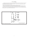
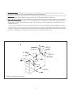
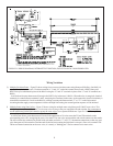
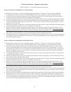
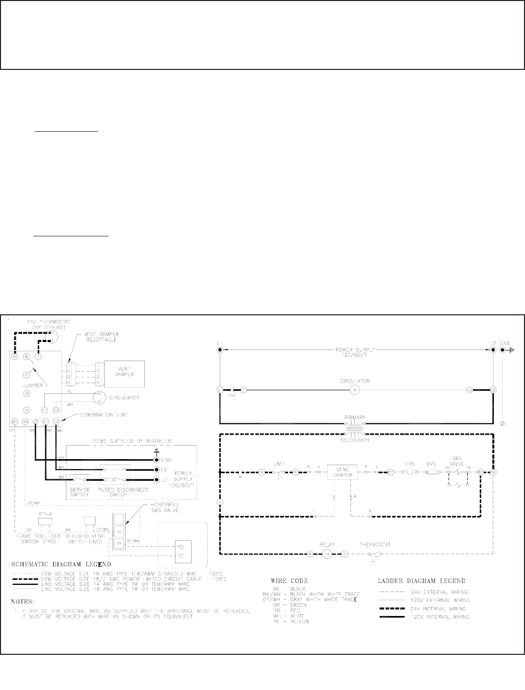
FIGURE 18: WIRING DIAGRAM, STANDING PILOT LESS TANKLESS HEATER
2
(NOTE 2)
2. VENT DAMPER REQUIRED ON ALL BOILERS EXCEPT CWI310 - CWI379. WHEN DAMPER
IS NOT USED, DAMPER HARNESS IS REPLACED WITH JUMPER PLUG
L
N
V8295A
(CWI310-379 ONLY)
NL
V8295A
GAS VALVE
(CWI310-379 ONLY)
19