


10
Remove the rope or pull tool from the end of the vent. 6)
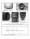
Verify that the Male Adaptor is undamaged. Lubricate the brown gasket in the female end of the Elbow with a few drops of water 7)
and insert the Male Adaptor fully into the Elbow.
Mount the bottom end of the PPs Flex Liner with the Elbow onto the Elbow Support Bracket installed in Step #2 using the Male 8)
Adapter Clamp as shown in Figure 1.9.
The cap provided with this kit is designed for installation over chimney crowns with round openings up to 12” and square 9)
openings having inside dimensions up to 8-1/2”. If the opening in the crown is larger than this, the installer must provide a
weather tight crown with an opening below these limits. The minimum diameter of the opening in this crown must be 6” for the
80mm PPs Flex Liner and 7” for 100mm PPs Flex Liner. Make such modifications to the crown in accordance with standard
practice before proceeding further.
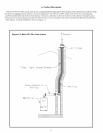
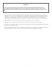
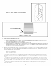
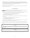
Cut the top end of the PPs Flex Liner so that it protrudes between 1-3/4” and 2-1/4” above the top surface of the crown (Figure 10)
2.0). Cut the pipe in one of the grooves using a sharp utility knife.
Install the Female Adaptor on the top end of the PPs Flex Liner using the same technique used to attach the Male Adaptor (Figure 11)
1.7). Allow the Female Adaptor to rest on Support Cross.
Apply a bead of weather resistant caulk or mortar to the crown and set the Lower Vent Cap flange on the crown so that the joint 12)
between the Lower Vent Cap flange and the crown is completely air and water tight. Anchor the Lower Vent Cap Flange to the
crown using an appropriate fastener through the knock-out in each corner.
Moisten the brown gasket in top of the Female Adaptor with a small amount of water and fully insert the Stainless Termination 13)
Pipe.
Slide the Upper Vent Cap over the Stainless Termination Pipe and snap in place on the Lower Cap. 14)
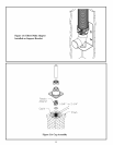
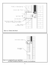
Provide a thimble for the penetration into the bottom of the chimney chase. This can be a section of smoke pipe, duct or ceramic 15)
chimney tile. It must be installed so that the following requirements are met (Figure 2.1):
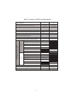
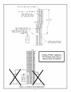
The inside dimensions of this thimble must meet the minimum chase ID requirements shown in Table 1.1.•
The thimble must be located so that a 5/8” in per ft. pitch can be maintained in the Vent Stub between the Elbow and •
Concentric Adaptor.
The thimble must be sealed to both the chimney flue and the exterior surface of the chimney using mortar or other suitable •
sealant having a service temperature rating of at least 210F.
The thimble must not protrude into the original chimney flue.•
Lubricate the gasket in the female end of the Vent Stub with a few drops of water and push it onto the Elbow. 16)
Mount the Exterior Wall Plate so that the Vent Stub will pass through the center of the opening in this plate when properly 17)
pitched. Anchor the Exterior Wall Plate to the wall using four masonry anchors, or other appropriate fasteners, capable of
supporting at least 40lbs each. Note: Exterior Wall plate must completely cover the thimble. Exterior Wall Plate can be cut down
as long as this condition is met. If the flange on the Concentric Adaptor is large enough to cover the thimble, the exterior wall
plate may be omitted completely. If the Exterior Wall Plate is too small to cover the thimble, a larger plate may be fabricated in
the field using 18GA (or heavier) galvanized steel. If the exterior wall plate is cut down or replaced, the Usage Warning Label on
the plate must be saved and attached to the base of the chimney near the concentric adaptor.
Seal the Exterior Wall Plate (if used) to the outer wall of the chimney using a suitable sealant having a service temperature rating 18)
of at least 210F.
Mark the Vent stub at a point 1” beyond where it exits the Exterior Wall Plate (Figure 2.1). Cut the Vent Stub squarely at this point 19)
with a fine tooth hacksaw or PVC saw. De-burr the cut end with a file, razor blade, or fine sandpaper.