


16
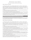
IX Indirect Water Heater Piping
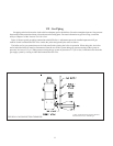
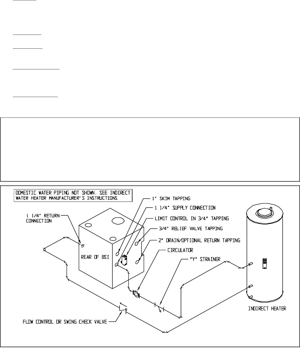
All BSI series boilers are equipped with tappings to permit the connection of a Crown Mega-Stor, or other indirect water
heater. In this type of system, hot boiler water is drawn from below the water line and passed through the heat exchanger in
the indirect water heater. This section describes boiler-side piping only. Refer to the indirect water heater instruction manual
for domestic water piping. The components in this system and their functions are as follows:
1)
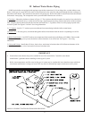
Circulator - Mount the circulator as shown in Figure 13. The circulator should be located as low and as close to the boiler
as practical. Do not install valves, or other devices having a significant pressure drop, between the boiler and the circulator
inlet. All piping between the boiler and the circulator inlet should be 1”, regardless of the size of the piping required in the
rest of the system. See Figure 15 in Part X for wiring information.
2) “Y” Strainer - Install a “Y” strainer to prevent sediment from accumulating inside the indirect water heater.
3) Check Valve - Prevents gravity circulation through the indirect water heater when the boiler is responding to a call for
heat.
4) Boiler Limit Control - Use a SPST break-on-rise temperature limit control such as the Honeywell L4006A. Do not set the
limit above 180F as doing so may cause the boiler to steam when there is no call for heat. See Figure 15 for wiring
information.
5) Valves and Unions - Install shut-off valves, drain valves, and unions in locations that will facilitate maintenance of the
system. Do not install any valves between the boiler and circulator inlet.
IMPORTANT
• Some indirect water heaters may not be suitable for use with a steam boiler. Consult the water heater
manufacturer’s guidelines before installing it in this type of system.
• Boiler water temperatures and flow rates in this type of system may be considerably lower than those upon which the
water heater manufacturer’s ratings are based. This may result in substantially longer water heater recovery times.
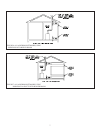
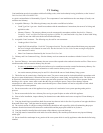
FIGURE 13: INDIRECT WATER HEATER BOILER-SIDE PIPING
15