


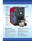
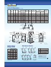
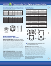

Series 24 Minimum Piping Recommendations – Water Boiler
Recommendation 1 is used
when the load is constant and
not varied due to mixing or
multiple zones. Use when:
■ system return water is not
less than 135° F for
prolonged periods of time
■ system flow does not impact
flow through the boiler
DRAIN VALVE
(SEE NOTE 4)
24-03 THRU 24-11 (W/20°F DROP)
24-03 THRU 24-12 (W/40°F DROP)
24-12 (W/20°F DROP)
DRAIN
VALVE
(SEE NOTE 4)
REAR OF
BOILER
REAR OF
BOILER
3” x 12” NIPPLE
AND BELL REDUCER
(SEE NOTE 3)
SUPPLY
RETURN
2
RETURN
RETURN
HEADER
RETURN
BRANCH
2
2A
23
2
1
2B
1
SUPPLY
1
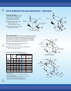
Recommendation 2 is a primary-secondary piping method
that maintains a constant flow through the boiler by using a
secondary boiler circulator. This arrangement isolates the
boiler from flow variations but does not safe-guard against
cold return water temperatures. Use when:
■ system return water is not less than 135° F
for prolonged periods of time
■ system flow does not impact flow through the
boiler (i.e. zoning, mixing)
BOILER CIRCULATOR
(BY OTHERS - SEE NOTE 5)
DRAIN VALVE
(SEE NOTE 4)
SUPPLY
SYSTEM PUMP
CLOSELY
SPACED
TEES
MAX
4D
BOILER CIRCUL
ATOR
(BY OTHERS - SEE NOTE 5)
DRAIN VALVE
(SEE NOTE 4)
SUPPLY
SYSTEM PUMP
CLOSELY
SPACED
TEES
MAX
4D
D
REAR OF
BOILER
RETURN
3” x 12” NIPPLE
AND BELL REDUCER
(SEE NOTE 4)
REAR OF
BOILER
RETURN
RETURN HEADER
RETURN BRANCH
2
2
2A
2B
1
23
2
1
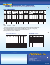
24-03 THRU 24-11 (W/20°F DROP)
24-03 THRU 24-12 (W/40°F DROP)
24-12 (W/20°F DROP)
RETURN PIPING SIZE (IN)
SUPPLY RETURN RETURN
PIPING HEADER BRANCH
SIZE (IN) (1) RETURN (2) (2A) (QTY.) SIZE (2B)
BOILER 20°F 40°F 20°F 40°F 20°F 20°F
MODEL DROP DROP DROP DROP DROP DROP
24-03 2 1-1/2 2 1-1/2 – –
24-04 2 1-1/2 2 1-1/2 – –
24-05 2 1-1/2 2 1-1/2 – –
24-06 2-1/2 1-1/2 2-1/2 1-1/2 – –
24-07 2-1/2 2 2-1/2 2 – –
24-08 2-1/2 2 2-1/2 2 – –
24-09 3 2 3 2 – –
24-10 3 2-1/2 3 2-1/2 – –
24-11 3 2-1/2 3 2-1/2 – –
24-12 4 2-1/2 4 2-1/2 3 (2) 3
Notes:
1. All piping is schedule 40.
2. Pipe sizes listed are based on a 20° F or 40°F differential (temperature drop).
Select one to match application.
3.
When specified return piping is less than 3”, install 3” x 12” nipple and appropriate
size bell reducer directly into boiler return tapping as shown.
4.
Drain valve—ball valve preferable, gate valve acceptable alternative
(supplied by others).—Minimum valve size per ASME code is 3/4 ” NPT.
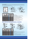
BOILER CIRCULATOR
(BY OTHERS - SEE NOTE 5)
DRAIN VALVE
(SEE NOTE 4)
SUPPLY
SYSTEM PUMP
CLOSELY
SPACED
TEES
MAX
4D
BOILER CIRCUL
ATOR
(BY OTHERS - SEE NOTE 5)
DRAIN VALVE
(SEE NOTE 4)
SUPPLY
SYSTEM PUMP
CLOSELY
SPACED
TEES
MAX
4D
D
REAR OF
BOILER
RETURN
3” x 12” NIPPLE
AND BELL REDUCER
(SEE NOTE 4)
REAR OF
BOILER
RETURN
RETURN HEADER
RETURN BRANCH
2
2
2A
2B
1
23
2
1
24-03 THRU 24-11 (W/20°F DROP)
24-03 THRU 24-12 (W/40°F DROP)
24-12 (W/20°F DROP)
PIPE SIZING AND NOTES FOR RECOMMENDATIONS 1 AND 2